MFJ-269 Instruction Manual HF/VHF/UHF SWR Analyzer
10
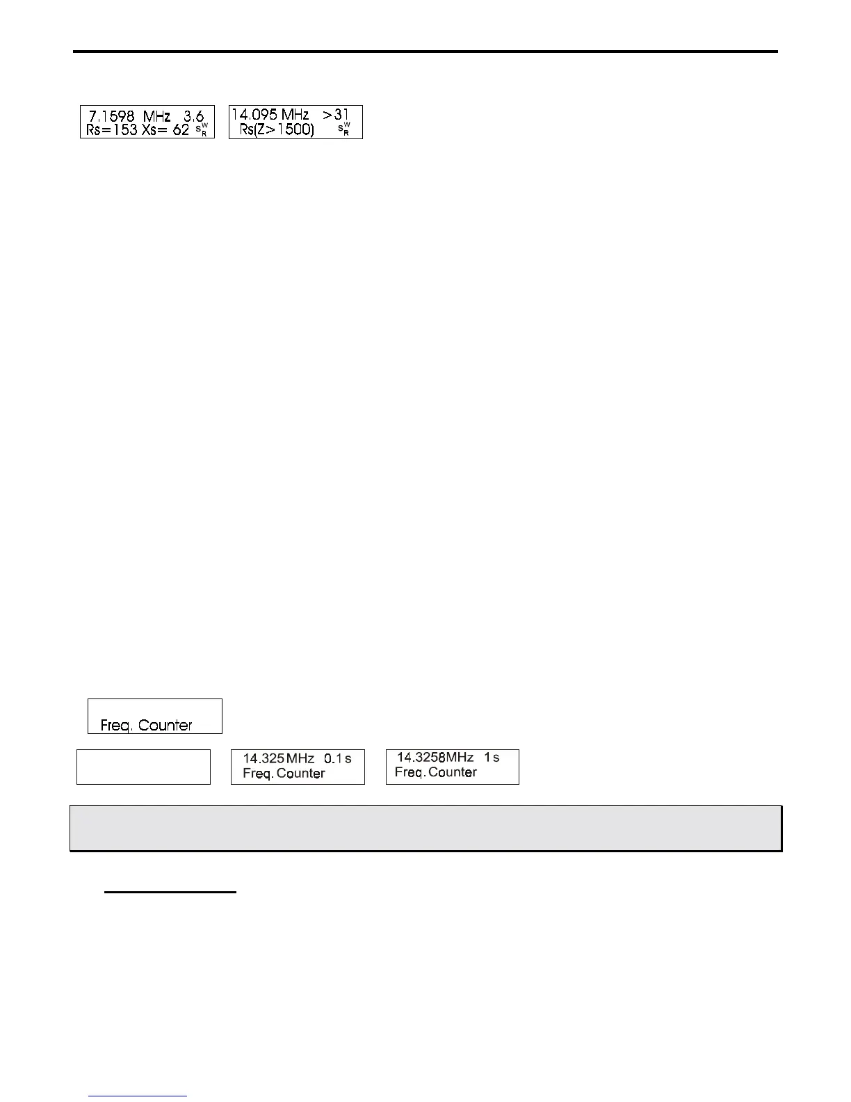
Note: Unless in the advanced modes, this unit displays load impedance in the conventional manner we
are all used to seeing. The standard way we describe impedance is a resistance in series with a
reactance.
SWR measurements in this menu are referenced or normalized to 50 ohms Zo., the normal impedance used in
transmitting systems.
Note: Advanced mode 3 allows measurement of SWR with lines other than 50 ohms Zo.
2.) Coax Loss
, the second mode, is reached by pressing the
“MODE”
button once. The liquid crystal display
(LCD) indicates the test frequency and approximate loss of any 50 ohm coaxial cable, attenuator pad, or
transformer or balun (for differential mode current only). In this mode, the 50 ohm device or cable under test
must not be connected or terminated by a load resistance at the far end. If the device under test is terminated in
anything that dissipates power, measured loss will be higher than actual loss.
Note: Advanced mode 3 allows measurement of loss in lines other than 50 ohms Zo.
3.) Capacitance in pF
is the third mode. The LCD shows measurement frequency, capacitive reactance (Xc=) in
ohms, capacitance (C=) in picofarads or pF. The
Impedance
meter indicates reactance in ohms, and the SWR
meter displays SWR.
4.) Inductance in
µH is the fourth mode. The digital display indicates measurement frequency, inductive
reactance (Xl=) in ohms, inductance (L=) in microhenries or µH. The
Impedance
meter indicates reactance in
ohms, the
SWR
meter displays SWR.
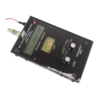
5.) Freq. Counter
is the fifth and final function of the main mode. The BNC connector labeled “
FREQUENCY
COUNTER INPUT”
should connect to the RF sample you want to measure. The sensitivity of this port ranges
from 10 millivolts at 1.7 MHz to 100 millivolts at 180 MHz. The
“GATE”
button controls the gate time of the
frequency counter. Longer gate times are accompanied by additional digits in the display, increasing counter
resolution.
14.32 MHz 0.01s
Freq. Counter
WARNING: NEVER APPLY MORE THAN TWO VOLTS OF PEAK VOLTAGE, OR ANY DC
VOLTAGE, TO THE FREQUENCY COUNTER BNC PORT.
3.4 UHF Operation
UHF Operation is selected while the
“UHF”
button on the upper left corner is depressed and locked. UHF
frequency adjustment is available by setting the
“FREQUENCY MHz”
switch to
“114-170 UHF”
position and
adjusting the
“TUNE”
knob. The display will give a warning if the frequency is outside the correct operating
range. Typical operating frequency range is 415 to 470 MHz.