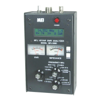
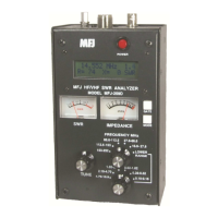
MFJ-269 Instruction Manual HF/VHF/UHF SWR Analyzer
21
This analyzer will determine the angle in degrees, but it will
not
describe the load reactance specifically as either
capacitive or inductive. It is a simple matter to determine the direction by adding a small amount of reactance in
series with the load and watching the angle change. If the angle decreases, the load reactance is opposite to the
sign or type of test reactance. If the angle increases, the load reactance is the same sign as the added reactance.
5.4.1.2 Series Equivalent Impedance
This
“ADVANCED 1”
display sub-mode is reached by pressing the
GATE
button once while in the
“Magnitude and Phase of Load Impedance”
mode. This mode displays the series equivalent impedance of the
load. This is the most common form used to describe antenna system impedance. In this mode, the load
impedance is described as a resistance in series with a reactance. In order to cancel the reactance without
changing the resistance, a reactance of the opposite type and same reactance value must be connected in
series
with the load at the point of measurement.
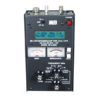
The digital display shows SWR, resistive part of load impedance (Rs=), and reactive part of load impedance
(Xs=). The
IMPEDANCE
meter displays the impedance (Z in ohms) while the
SWR
meter displays 50 ohm
referenced SWR.
Series equivalent impedance display examples:
7.1598 M Hz 3.2
Rs= 50 Xs= 62
14.095 M Hz > 31
Rs(Z> 1500)
s
W
R
s
W
R
With impedances in the above left-hand display, resistance would remain 50 ohms, reactance would go to zero,
and SWR to 1:1 if an opposite-sign reactance of 62 ohms was connected in
series
with the feedline at the point
where the measurement was made.
Note: Every series impedance has a parallel equivalent counterpart. A series impedance of Rs 50 Xs
62 is equal to the parallel equivalent impedance of Rp 126 Xp 102 ohms. This analyzer can
make that conversion in this mode by pressing the GATE button. See 5.4.1.3
5.4.1.3 Parallel Equivalent Impedance
Pressing the
GATE
button twice from the
Magnitude and Phase of Load Impedance
mode toggles the analyzer
into a parallel equivalent impedance sub-mode.
Parallel equivalent display examples:
7.1598 M Hz 3.2
Rs= 126 Xs= 102
14.095 M Hz > 31
Rs(Z> 1500)
s
W
R
s
W
R
In the left hand display example, the equivalent parallel resistance is R=126 ohms. That resistance appears to be
in
parallel
with 102 ohms. If we
parallel
connect an opposite-sign reactance of 102 ohms, the
parallel
equivalent
reactance is canceled. Only the 126 ohm resistance remains.
This is a powerful tool used in matching antennas. The MFJ-269 places that tool at your fingertips. By checking a
load for both Rp and Rs, you can see if either is close to the desired resistance. If one resistance value is close to
the desired value, adding only one component will match the load by canceling reactance.


 To Next Page