MFJ-269 Instruction Manual HF/VHF/UHF SWR Analyzer
15
Note:
The MFJ-269 measures reactance, and converts reactance to capacitance. The MFJ-269 can not determine
if the reactance is actually inductive or capacitive. You can usually determine the type of reactance by
adjusting frequency. If frequency is increased and reactance (X on the display or Impedance on the
meter) decreases, the load is capacitive at the measurement frequency. If frequency is reduced and
reactance decreases, the load is inductive at the measurement frequency. This does NOT apply to
antennas and also to other loads when they viewed through a transmission line more than a small fraction
of a wavelength long.
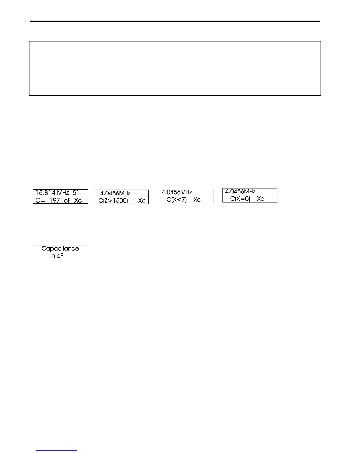
“Capacitance in pF”
is the third mode. It measures capacitance values (in pF) at whatever frequency you select
on the display. Normal measurement range is from a few pF to a few thousand pF. The front panel
IMPEDANCE
meter indicates reactance (X in ohms) of the capacitor.
Note: It is normal for the reactance of a capacitor to change gradually with frequency. This effect
occurs because series inductance in the leads and sometimes in the capacitor causes effective
capacitance to change with frequency.
The MFJ-269 becomes inaccurate measuring reactances below 7 ohms or above 1500 ohms. If the reactance of
the component is outside reliable ranges,
“C(X<7) [X]”
or
“C(Z>1500)”
will be displayed. When the warning is
displayed, capacitance is not measured.
To measure capacitance:
a.) Turn the MFJ-269 on and step through with the mode switch until the
“Capacitance in pf”
display appears.
b.) Connect the capacitor across ANTENNA connector with the shortest leads possible, or with the lead length
normally used in the working circuit.
c.) Adjust the MFJ-269 to a frequency near where you plan to use the component, but be sure the unit does not
produce a range warning.
“C(Z>1500)”
warning indicates the measurement frequency is too low, and
“C(X<7)”
is a warning that indicates the frequency is too high.
“C(X=0)”
indicates the capacitor appears to be a near
perfect short at the operating frequency of the MFJ-269. It means either the capacitor is shorted, the measurement
frequency is too high, or the capacitor value is too large to be measured.
Note: At higher frequencies the effective capacitance increases, reaching infinite capacitance when the
capacitor and stray inductance becomes series-resonant.
The frequency where the capacitor’s impedance, and the leads connecting to the capacitor, becomes
(X=0) is the series resonant frequency. Bypass capacitors are sometimes intentionally operated
at or near the series or self resonant frequency, but most applications are at frequencies far
below the series resonant frequency.
4.2.4 Inductance