MFJ-269 Instruction Manual HF/VHF/UHF SWR Analyzer
9
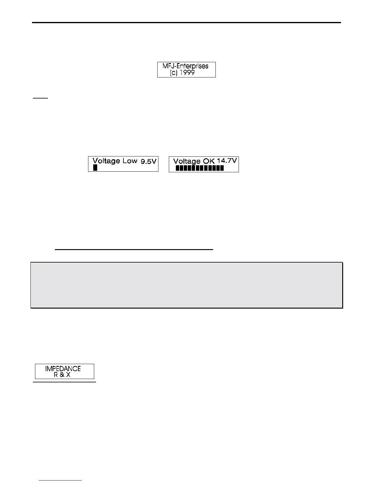
The second message is the software copyright date.
Note
:
Pressing the
“MODE”
button before applying power or turning the
“POWER”
switch on, and
continuing to hold the
“MODE”
button down until the copyright message appears, causes a
"POWER SAVING OFF" message to appear just as the
“MODE”
button is released. This
message appears just before the voltage check. This message confirms the battery saving
“sleep mode” has been disabled.
The third message is a voltage check. It displays the operating voltage, indicating battery charge or external
power supply voltage.
The final power-up display is the “working” display described in 3.3 (Impedance R&X) below.
Two panel meters indicate SWR and Impedance of loads connected to the
“ANTENNA”
port.
If you press the
“MODE”
button after the operating display is up, the mode changes. After releasing the
“MODE”
button, the display will show the type of data measured in the newly selected mode step. The five main
(or opening) measurement modes are described below.
3.3 Main MODE descriptions (HF Functions Only)
CAUTION: THERE IS A ‘‘UHF’’ SWITCH LOCATED AT THE UPPER LEFT-HAND
SIDE OF THE ANALYZER. THIS SWITCH SHOULD BE PRESSED AND
LOCKED FOR UHF OPERATION ONLY WHEN UHF OPERATION IS DESIRED
AND ONLY AFTER THE UNIT IS POWERED UP. FOR INFORMATION ON
UHF OPERATION, SEE SECTION 3.4
Mode is changed by momentarily pressing the
“MODE”
button during normal operation. As the mode changes, a
description of the mode appears on the screen for a few seconds. The five “Main menu” display modes are
described below:
1.)
The initial power-up mode is
Impedance R&X
. When initialized, the following message appears briefly on
the front panel display:
In this mode, the MFJ-269 LCD (liquid crystal display on front panel) shows frequency in MHz, SWR, the
resistive part of load impedance (R=), and the reactive part of load impedance (X=). The IMPEDANCE meter
displays the complex impedance (Z in ohms), and the SWR meter displays SWR.