MFJ-269 Instruction Manual HF/VHF/UHF SWR Analyzer
2
5.4.1.4 Return Loss and Reflection Coefficient…………..20
5.4.1.5 Resonance Mode………………………………….20
5.4.1.6 Match Efficiency ………………………………..21
5.4.2 UHF Advanced 1………………………………………………….
5.4.2.1 Return Loss and Reflection Coefficient (UHF) …..
5.4.2.2 Match Efficiency (UHF)……………………..
5.5 Advanced 2…………………………………………………………….21
5.5.1 Distance to Fault (DTF) (for HF/VHF only)…………………
5.5.1.1 DTF balanced lines………………………………22
5.5.1.2 DTF Coax lines…………………………………..22
5.5.1.3 DTF Antenna Length……………………………..23
5.5.1.4 DTF measurement procedures…………………….23
5.5.2 Calculator Functions
5.5.2.1 Line Length in degrees……………………………………….
5.5.3.2 Line length in feet …………………………………………….
5.6 Advanced 3 (for HF/VHF only)…………………
5.6.1 Z Characteristic…………………………………..25
5.6.2 Coax Loss ………………………………………..25
6.0 Adjusting Simple Antennas
7.0 Testing and Tuning Stubs and Transmission Lines
8.0 Technical Assistance
INTRODUCTION
Attention
:
Read section 2.0 before attempting to use this product.
Incorrect power supply
voltages
or excessive
external voltages applied to the ANTENNA connector
will
damage
this unit.
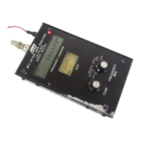
1.0 Description
The MFJ-269 RF analyzer is a compact battery powered RF impedance analyzer. This unit combines
five basic circuits; a variable oscillator, frequency counter, frequency multiplier, 50 ohm RF bridge, a
twelve-bit A-D converter, and microcontroller. This unit performs a wide variety of useful antenna
and RF impedance measurements, including coaxial cable loss and electrical distance to an open or
short.
Primarily designed for analyzing 50 ohm antenna and transmission line systems, the MFJ-269 also
measures RF impedances between a few ohms and several hundred ohms. An easily accessed user-
controlled Zo setting in the
ADVANCED
function menus allows changing SWR and other SWR
functions (i.e. return loss, reflection coefficient, match efficiency, etc) to any normalized impedance
value between 5 and 600 ohms.