MFJ-269 Instruction Manual HF/VHF/UHF SWR Analyzer
39
A
B
C
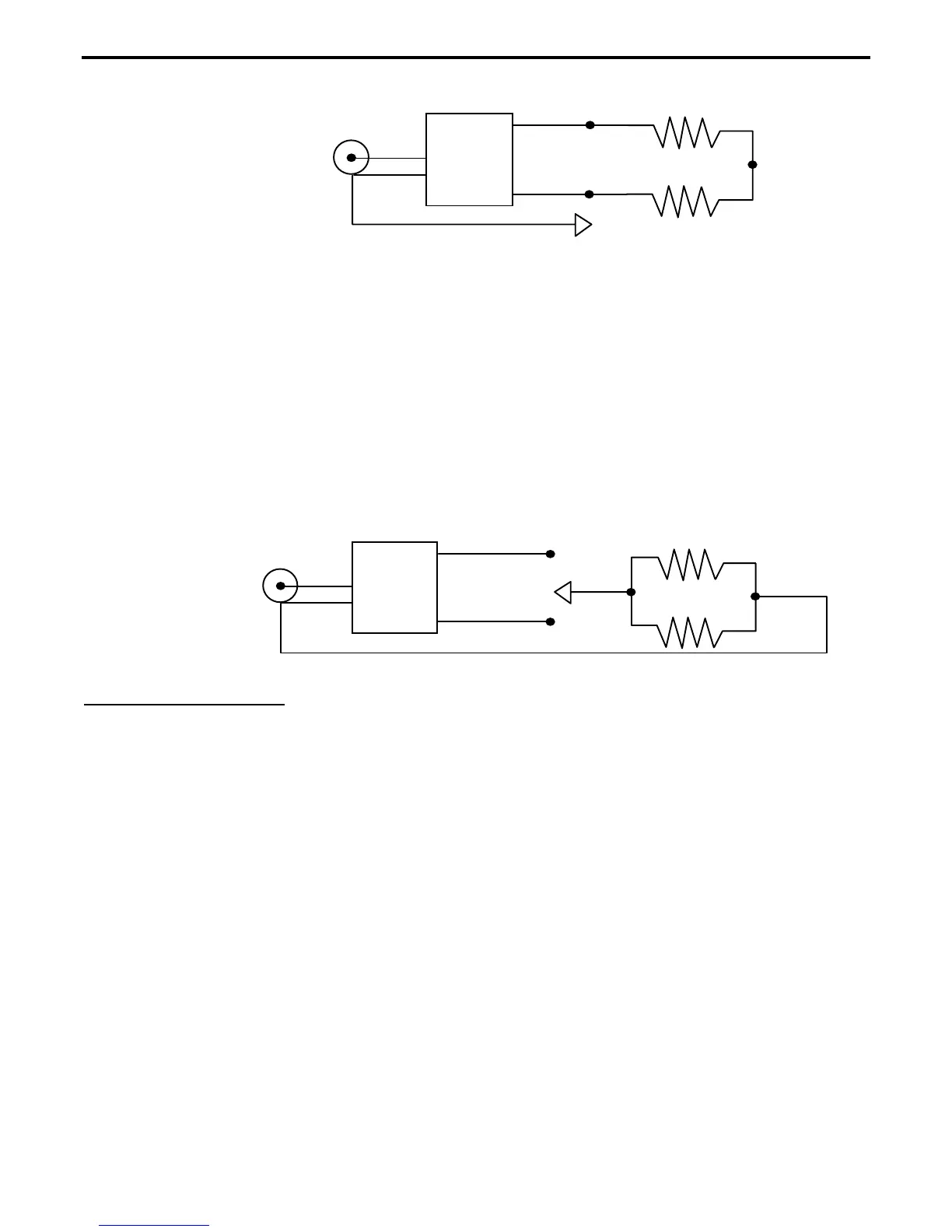
BALUN
Clip Lead
"ANTENNA"
To the MFJ-259B's
connector
A properly designed
current balun
is the type most effective for maintaining current balance. It has the highest
power capability and lowest loss for given materials. It should show a low SWR over the entire operating range
of the balun with the clip lead in
any
of the three positions.
A well designed
voltage balun
should show a low SWR over the entire operating range when the clip lead is in
position "B". That SWR should not change when the clip lead is removed. It will show a very poor SWR when
the clip lead is in position "A" and "C". SWR should be about the same in either position “A” or “C”. If the balun
does not follow these rules, the balun has poor balance and is of questionable benefit.
A 4:1 voltage balun should also be tested by disconnecting the outer connections of the two resistors and
connecting each resistor in parallel. If the voltage balun is operating properly the SWR will be very low with the
resistors connected from either output terminal to ground.
Voltage balun test only:
BALUN
"ANTENNA"
To the MFJ-259B's
connector
7.8 Testing RF Chokes
Large RF chokes usually have frequencies where the distributed capacitance and inductance form a low
impedance “series-resonance”. This series resonance occurs because the choke acts like a series of back-to-back
L networks. This causes three problems:
First, impedance from end to end in the choke becomes very low.
Second, the voltage at the center of the resonant point becomes very high, often causing severe arcing.
Third, the current in the winding becomes very high, often resulting in severe heating.
Troublesome series-resonances can be detected by installing the choke in the operating location, and connecting
only
the MFJ-269 from end-to-end of the choke through a short 50 ohm jumper cable. By slowly sweeping the
operating frequency range of choke, dips in impedance identify low impedance series-resonant frequencies.
By moving a small insulated screwdriver’s blade close to and along the choke, you will find a point where the
series-resonant impedance suddenly changes. This is the area that has the highest voltage and also the area where
adding or subtracting a tiny amount of capacitance has the largest effect. By removing turns to reduce
capacitance or adding a small capacitive stub at this point, resonance can be shifted out of the desired frequency
range.
 Loading...


