MFJ-269D Instruction Manual LF/HF/VHF/UHF SWR Analyzer
8
4. Inductance in µH: The fourth mode, Frequency appears on top and XL (inductive reactance) on the
bottom. Meter shows reactance (X).
5. Freq. Counter: The fifth function turns off the analyzer's internal oscillator and routes the input of the
counter to the BNC connector labeled Frequency Counter Input. In this mode, the top line of the LCD
display shows the measured Frequency in MHz and the counter's Gate Time in seconds.
Important Note: Section-4 of this manual provides detailed instructions for using each of the five basic
operating modes described above. To ensure accurate measurement and avoid the possibility of
inadvertent damage, please read through this section carefully before operating the analyzer!
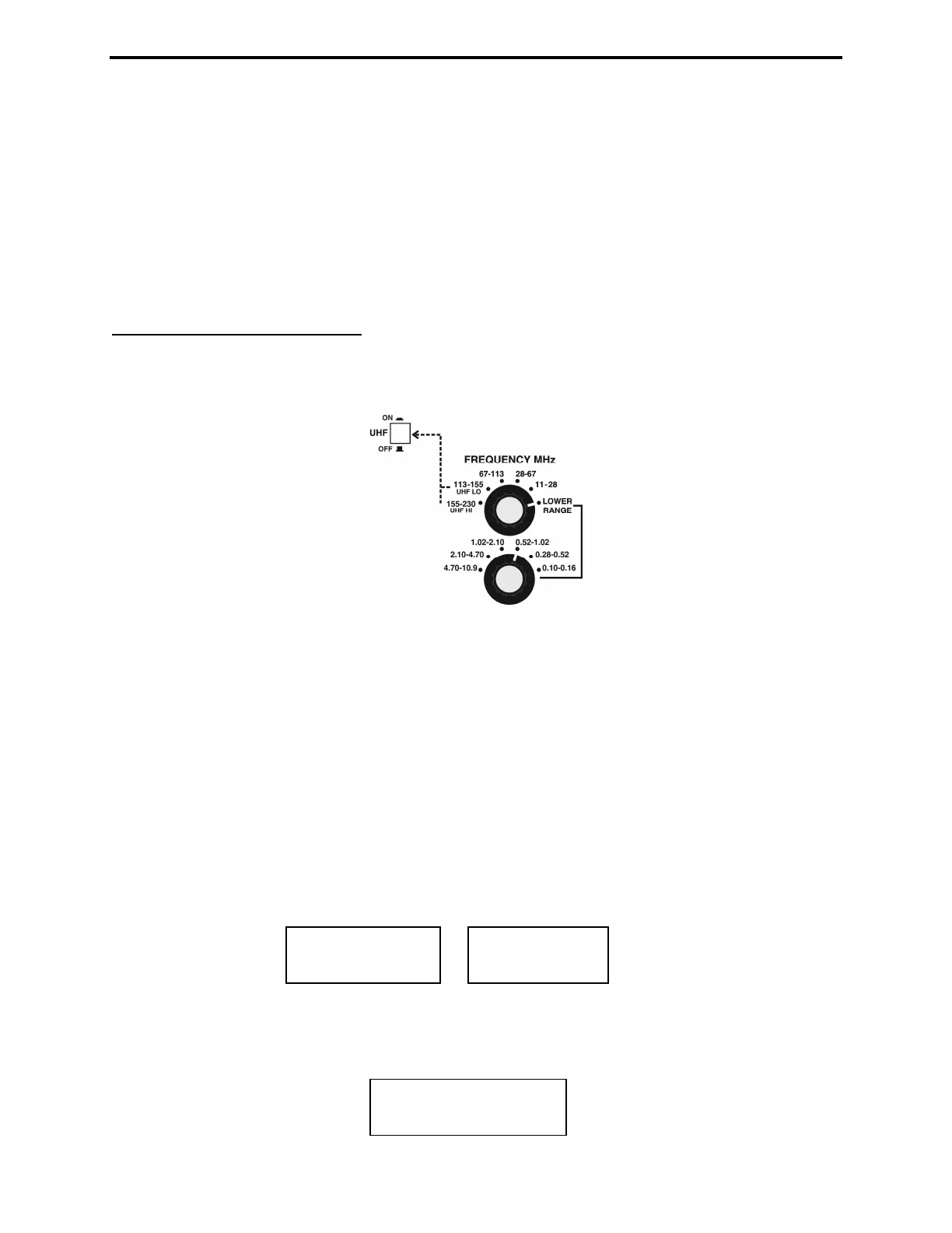
3.4 Frequency Control
The MFJ-269D tunable RF-oscillator covers an exceptionally wide frequency span, using two rotary
band switches for LF/HF/VHF coverage (0.10-230 MHz) -- plus an additional pushbutton switch to
activate UHF coverage (415-470 MHz) .
1. LF, HF and VHF Operation: The Lower Range rotary switch selects four LF and HF bands (0.10-
11.0 MHz). The Upper Range switch selects 5 HF and VHF bands for 11-230 MHz coverage. Note that
the Upper Range switch must be set fully clockwise to the Lower Range position for the lower-range
band selector to function. The variable Tune control (VFO capacitor) provides a small overlap at each
band edge to ensure gap-free tuning across the spectrum.
2. UHF Operation: UHF coverage is broken into two bands. To measure UHF SWR (415-490 MHz),
first press in the UHF switch located just above the LCD display. Then, for 415-470 MHz coverage, set
the upper Frequency MHz switch to the 113-155 MHz band (UHF LO). For 470-490 MHz coverage,
set the upper Frequency MHz switch to 155-230 MHz. (UHF HI).
It is normal for the VFO's Tune range to exceed the analyzer's usable UHF measurement range. If the
VFO frequency is out of range in UHF Mode, one of the error messages shown below will instruct you to
increase or decrease frequency to bring it back in range:
Adjust Tune clockwise to increase frequency and counterclockwise to decrease frequency. When in
range, the operating Frequency will appear on the top line of the LCD display -- along with the SWR
reading. The bottom display line becomes an analog SWR bar-graph (see below).
445.75 MHz 1.3
INCREASE
FREQUENCY
DECREASE
FREQUENCY