MFJ-269D Instruction Manual LF/HF/VHF/UHF SWR Analyzer
16
5.4 Advanced -1 Modes
5.4.1 Advanced 1 (LF/HF/VHF)
Advanced-1 Mode measures impedance and SWR functions. To enter Advanced-1, press and hold down
the Mode and Gate buttons simultaneously for approximately two seconds.
Advanced 1
There are six display functions available within this mode (see list below):
Magnitude and phase of load impedance (5.4.1.1)
Series Equivalent impedance (5.4.1.2)
Parallel Equivalent impedance (5.4.1.3)
Return loss and Reflection coefficient (5.4.1.4)
Resonance (5.4.1.5)
Match efficiency (5.4.1.6)
To return to the Main (or Basic) menu, press and hold the Mode and Gate buttons to step through the
Advanced-2 and Advanced-3 screens.
5.4.1.1 Magnitude and Phase of Load Impedance
Magnitude and Phase of Impedance is the first selection in the Advanced-1 menu, and it comes up
automatically upon entering Advanced-1 Mode. If already using one of the Advanced-1 functions, you
may "step" or "scroll" to the Magnitude and Phase of Impedance mode by holding down Mode and Gate
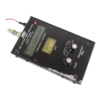
switches. The opening display first indicates:
and then flashes to:
In this mode, the LCD displays Frequency, Impedance Magnitude (Z) (in ohms), and Phase Angle of the
Impedance (θ). The meters indicate 50-ohm normalized SWR and the load Impedance (Z). The
maximum impedance limit is set at 1500 ohms. Exceeding this limit results in an impedance display of
(Z>1500).
Note: Stray connector capacitance will be lower than 1500 ohms at frequencies higher than 30 MHz, and
lower as adapters and leads are added to the Antenna port. This small stray capacitance will not affect
high frequency measurements, and produces only minor errors in measurement of impedances under a
few hundred ohms at VHF.
Phase angle of Impedance is another way of expressing R and X. Instead of providing R and X as
separate numerical quantities, it presents a vector-type description of measured impedance. Impedance
(Z) is still described as the length (magnitude) of a line representing the complex impedance (this is the
same Z as given in other functions). Besides Z, an angle between zero and 90 degrees is shown. This
angle represents the phase difference between current and voltage at the terminals of the analyzer.