MFJ-269D Instruction Manual LF/HF/VHF/UHF SWR Analyzer
4
is individually compensated to provide the best detector linearity possible. Small errors may also occur
during A/D conversion due to practical limitations on bit resolution.
Connection lengths: Connection lengths both inside and outside the analyzer bridge can upset readings,
especially at higher frequencies and when impedance is very high or very low. The MFJ-269D minimizes
internal problems by using surface mount low capacitance microwave components with nearly zero lead
length. It's important to remember that any external leads you add, even short leads, will modify the
impedance of the load at radio frequencies. To obtain highest accuracy, always use the shortest test
cables possible with the fewest connectors and adapters in the line.
Note: Some handheld analyzers display erroneous readings falling outside the reliable measurement
range, presenting that data numerically -- as if it were "factual". The MFJ-269D is designed to avoid such
errors by displaying an on-screen warning (Z > 1500) anytime data falls outside the unit's accurate
measurement range.
2.0 POWER SOURCES
This section describes power supply and battery selection.
READ THIS SECTION BEFORE CONNECTING THIS DEVICE TO ANY POWER SOURCE. IMPROPER
CONNECTIONS OR INCORRECT VOLTAGES MAY CAUSE DAMAGE TO THIS PRODUCT!
2.1 External Power Supply
The MFJ-1312D satisfies all external voltage and current power source requirements and we highly
recommend using it with your MFJ-269D. External power requirements are as follows:
1. When the unit is ON, supply voltage must be over 11 volts but not exceeding 16 volts.
2. When in Sleep Mode or OFF (supply lightly loaded), voltage must not exceed 18 volts.
3. The supply must be well filtered against hum and noise.
4. The MFJ-269D case (chassis ground) must be connected directly to the supply's negative terminal.
5. The supply must not have a grounded positive lead (- center pin).
6. The "ideal" supply voltage is 13.8 volts dc.
7. When rechargeable batteries are used, 14 volts or higher is required for charger operation.
8. Current demand is 150 mA (max) on HF and VHF, 250 mA (max) on UHF.
WARNING: READ SECTION 2.2 THROUGH 2.4 (BATTERY INSTALLATION INSTRUCTIONS)
BEFORE INSTALLING BATTERIES.
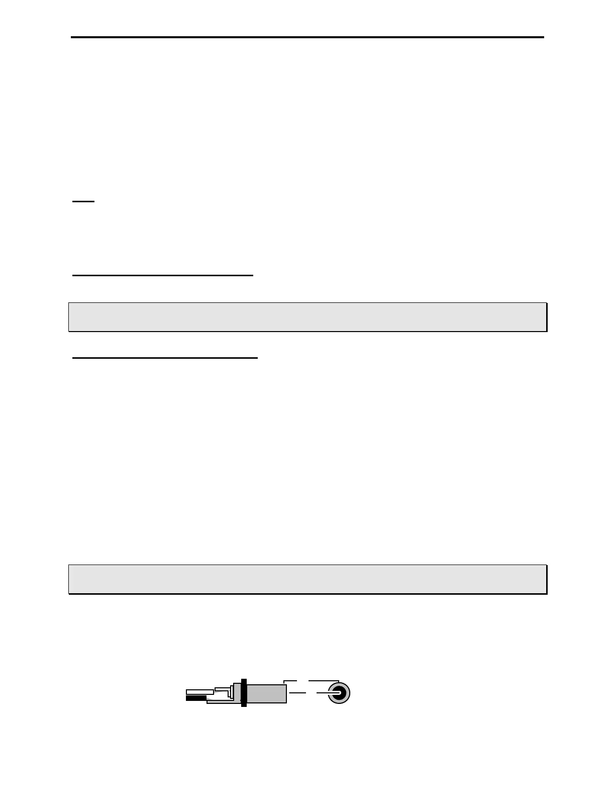
The MFJ-269D has a recessed 2.1 mm power receptacle near the RF connectors. This receptacle is
labeled POWER 13.8 VDC. The outside conductor is negative, the center is positive. Inserting a
power plug in the POWER 13.8 VDC receptacle disables internal batteries as the analyzer's power
source. However, the internal batteries will still be trickle charged when the power supply plug is
inserted into the unit. Power plugs must be wired as shown below:
+
-
+
-
2.1 mm