MFJ-269D Instruction Manual LF/HF/VHF/UHF SWR Analyzer
10
1. If your antenna doesn't have a dc-grounded feed system, momentarily short the cable's center
conductor to the shield immediately before connecting up to the analyzer. This simple procedure will
discharge any static buildup on the antenna and prevent damage to the analyzer's sensitive detector
diodes.
2. Connect the antenna lead to the analyzer's N-Female Antenna connector.
3. Set the VFO's two Frequency selector band switches for the appropriate range.
4. Turn on the Power switch while watching the display. Battery voltage should read OK (11-16 volts).
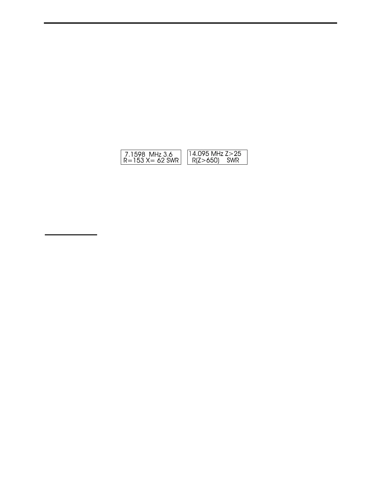
5. Following the boot screens, the default mode will come up with the working screen for Frequency,
SWR, Resistance (R), and Reactance (X). The SWR and Impedance analog meters will also
become active.
6. Adjust Tune (the VFO capacitor) as needed to find your desired test frequency -- or tune until you
obtain a minimum SWR reading.
Note that the MFJ-269D also has Advanced antenna-measurement modes that are described in detail in
Section-5.0. However, unless you have a strong working knowledge of RF systems, you may find these
added modes of limited value. Most represent more technically sophisticated ways of expressing the
same data offered by the basic modes.
Antenna hints:
1. Measuring Antenna Impedance: For complex impedance measurements, always install the analyzer
as close as possible to the element's feedpoint (within or 1-2 degrees of phase shift). Alternatively, you
may use a precisely cut 1/2-wavelength of cable displace the calibration plane by a controlled amount
(360-degree phase rotation).
2. Electrical Half-Wavelengths of Cable: Installing a half-wavelength of cable between the load and
the analyzer will rotate phase a full 360 degrees so that no apparent transformation takes place in the line.
However, the response will only be transparent on one discrete frequency. Even a small frequency
change will begin to skew your impedance readings and may even shift the antenna's resonant frequency
as the cable begins to introduce its own reactance into the system. Phase errors compound with multiple
half-wavelengths, so limit cable length to one or two phase rotations at most!
3. SWR, Resonance, and Impedance: It's always preferable to measure SWR rather than resonance or
impedance magnitude (Z) as the standard for adjusting your antenna.
By definition, minimum SWR (1:1) and maximum power transfer occur when the source, transmission
line, and load impedance are all of equal value (conjugate match).
Resonance occurs when reactance fully cancels at the antenna's feedpoint, causing the load to become
purely resistive (Xc + XL = 0).
Although Minimum SWR and Resonance often coincide, they are not directly correlated and rarely will
occur on exactly the same frequency. If your antenna doesn't happen to present a 50-ohm load at
resonance, there will still be resistive mismatch (and SWR) in the system. In fact, slightly lower SWR
may actually occur on some other frequency. By the same token, if you adjust your antenna for an
Impedance reading of 50 ohms, it may have a substantial reactive component (for example R = 46, X =
17) that would elevate SWR and shift the minimum-SWR point to a different frequency.