MFJ-784B Instruction Manual
Installation Error! Main Document Only.-2
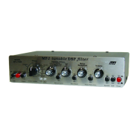
Back Panel Connections
Power
: This connector supplies power to the unit. It connects to a 2.1 mm
coaxial plug with the center conductor positive and the shield ground. An
optional dc supply, the MFJ-1315, is available from MFJ. The voltage
should be 10-16 Vdc.
If the power supply voltage drops below 10 volts
the MFJ-784B will perform erratically.
Warning:
V
oltages greater than 18 volts or reverse polarity may
permanently damage the MFJ-784B.
Headphones Out: This jack supplies volume controlled audio for headphones. It
accepts standard male 1/4 inch stereo or mono phone plugs and
provides audio to both stereo and mono headphones.
Speaker Out: This jack supplies volume controlled audio for a speaker with a
3.5 mm stereo or mono phone plugs. Disengaging the Speaker button
disables this jack.
Filtered Audio Adjust: This adjustment varies the level of the audio outputs to
Filtered Audio Out and pin 4 of the To TNC port.
Filtered Audio Out: This jack supplies line level audio for tape recorders or
audio amps. It is a standard RCA phono jack. A quality shielded cable
should be used for connections to this jack. The output is dependent on
the Filtered Audio Adjust and independent of the DSP's volume control.
Receive Audio Adjust: This adjustment controls the sensitivity of the Receive
Audio In jack and pin 4 of the To Radio port. Proper adjustment is
achieved if the Input Level indicator flashes mostly green and never red
when the receiver's volume is at normal levels. Refer to page 2-4.
Receive Audio In: This jack is normally connected to the receiver's speaker or
headphones output. It is a standard RCA phono jack. A shielded cable
should be used to connect this connector to the station receiver.
To Radio: This port supplies connections for transmit and receive audio. PTT is
connected directly to the To TNC port. A connection is also available for
a T/R line to automatically bypass the filter during transmit.
To TNC: This port supplies connections to the filtered audio output and the
transmit audio inputs. PTT is connected directly to the To Radio port.