MFJ-941EK Tuner Kit Instruction Manual
- 17 -
CONSTRUCTION
Like the Inductor switch, the Transmitter and Antenna tuning capacitors are
isolated from the chassis by non-conductive washers. The Transmitter control
uses fiber washers and the Antenna control uses Teflon washers. Find the
following items:
(2) 12-313 pF air-variable capacitors
(2) 3/8" Hex Control Nut, Panel Mount
(2) 3/8" ID x 5/8" OD Flat Washer, Metal
(1) 3/8" ID x 5/8" OD Flat Washer, Fiber
(2) 3/8" ID x 3/4" OD Flat Washer, Fiber
(1) 3/8" ID x 5/8" OD Flat Washer, Teflon
(2) 3/8" ID x 3/4" OD Flat Washer, Teflon
Flat 3/4" Insulating Washer
Flat 5/8" Metal Washer
Control Nut
Flat 5/8" Insulating Washer
Flat 3/4" Insulating Washer
Stator
Rotor
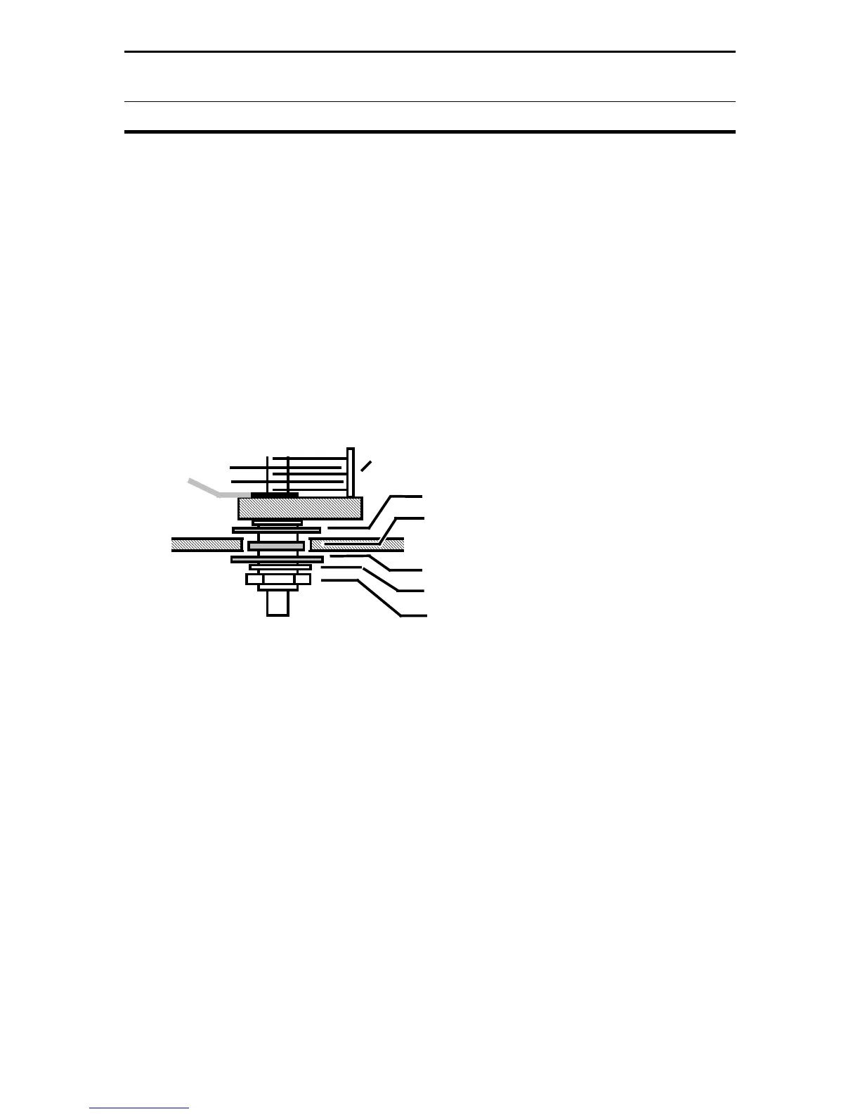
Diagram 11: Capacitor Mounting
[ ] Install a 3/4" fiber flat washer on one of the variable capacitors.
[ ] Insert the shaft at TRANSMITTER with the stator to the right side, as shown in
Diagram 11.
[ ] From the front, install a 5/8" fiber washer, centering it in the hole.
[ ] Install a 3/4" fiber flat washer, a 5/8" metal washer, and a control nut. Secure.
Repeat the same procedure for the Antenna capacitor using the three Teflon flat
washers.
[ ] Install the other capacitor at ANTENNA, as shown.
 Loading...