MFJ-941EK Tuner Kit Instruction Manual
- 18 -
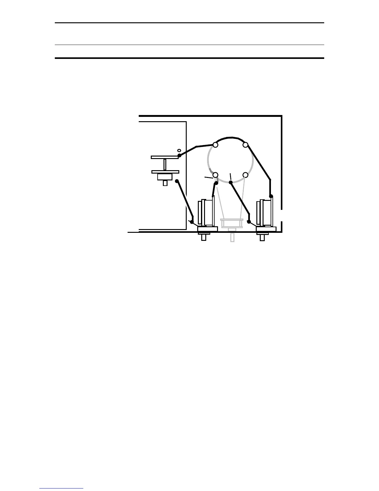
CONSTRUCTION
Looking at the coil assembly, you'll see that the top winding has been cut and is
isolated from the remainder of the coil. This wire is used to connect the stator of
C1 to the pc board. It will be pulled back from the two front retainer rods and
routed as shown below in Diagram 12:
C1
Stator
Rotor
Solder to Switch
Tab Adjacent
To C1
Antenna
Capacitor
Coil Wire
Buss
Wire
Buss
Wire
C2
Stator
Rotor
Tap
Coil
Top
of
Coil
Onto
End
Diagram 12: Wiring Detail
[ ] Carefully remove the top wire from the two front retainers, as shown.
[ ] Trim and install the right lead end to the stator of the Antenna capacitor.
[ ] Trim and solder the left lead-end to the switch tab adjacent to C1 at SW4*
*The pad at legend C1 and the exposed tab on SW4 are common to each other.
Connecting the buss wire directly to the switch tab is simpler than lifting the
board to solder it in at C1.
To complete tuner wiring, find the remaining #16 buss wire.
[ ] Trim and install a buss wire onto the rotor tab of the Antenna capacitor.
[ ] Install the opposite end as a tap on the exposed inductor winding, as shown.
Locate the left front retaining rod of the Inductor. There will be a curled-back
wire-end at that location. That is the top end of the tuner coil.
[ ] Install a length of buss wire onto the top winding of the coil (at left-front rod).
[ ] Trim and install the opposite end to the Transmitter capacitor stator post.
[ ] On the pc board, find the buss wire installed at C2.
[ ] Install the opposite end to the Transmitter capacitor rotor tab (C2).
 Loading...