MFJ-941EK Tuner Kit Instruction Manual
- 29 -
OPERATING INSTRUCTIONS
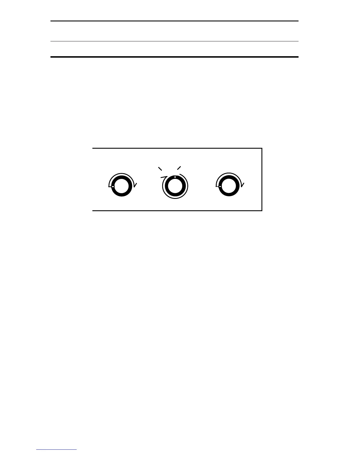
less inductance at high frequencies. Rotating the knob clockwise -- from A
toward L -- progressively decreases inductance and increases the tuner's
operating frequency.
[ ] The Transmitter and Antenna capacitors deliver maximum capacitance at
"0" and minimum capacitance at "10". This labeling may sound reversed until you
consider that more coupling is needed at lower frequencies and less is needed at
higher frequencies. Typically, we associate higher frequencies with a clockwise
turn of the knob (see below):
Freq
L
Hi Freq
Lo Freq
A
Lo
Freq
Hi
Freq
Lo
Freq
Hi
TRANSMITTER INDUCTOR
ANTENNA
[ ] When tuning a T-network, start with a little more capacitance (tighter coupling)
than you might actually need for your final match. Tighter coupling reduces the
chance of arcing. Some users have suggested pre-setting capacitors fully
meshed (0) for 160 and 75 meters, 3/4 meshed (2.5) for 60-20 meters, and 1/2
meshed (5.0) for 20-10 meters before starting to tune.
[ ] Once the capacitors are pre-set, find a staring point for the Inductor control by
listening in receive mode and finding the switch position that yields the strongest
background noise.
[ ] After the Inductor switch is set for highest background noise, apply a low-
power carrier and alternately adjust Transmitter and Antenna for minimum SWR.
If SWR won't approach 1:1, reset the Inductor switch by one step and try again. If
the minimum SWR is higher still, go the opposite way. Keep the power level low
until SWR is nulled down to a relatively low level.
[ ] Very often, there will be more than one inductor setting that will yield low
SWR. With T networks, it's always advisable to use the minimum amount of
inductance and the maximum amount of capacitance needed to obtain a good
match. Loosely coupled higher-Q settings may yield acceptable SWR, but it
increases the risk of arcing at high power. Think "C high, L low"!
 Loading...