6 – CS 300 Gate Controls / rev. 04.06
5. Initial Operation
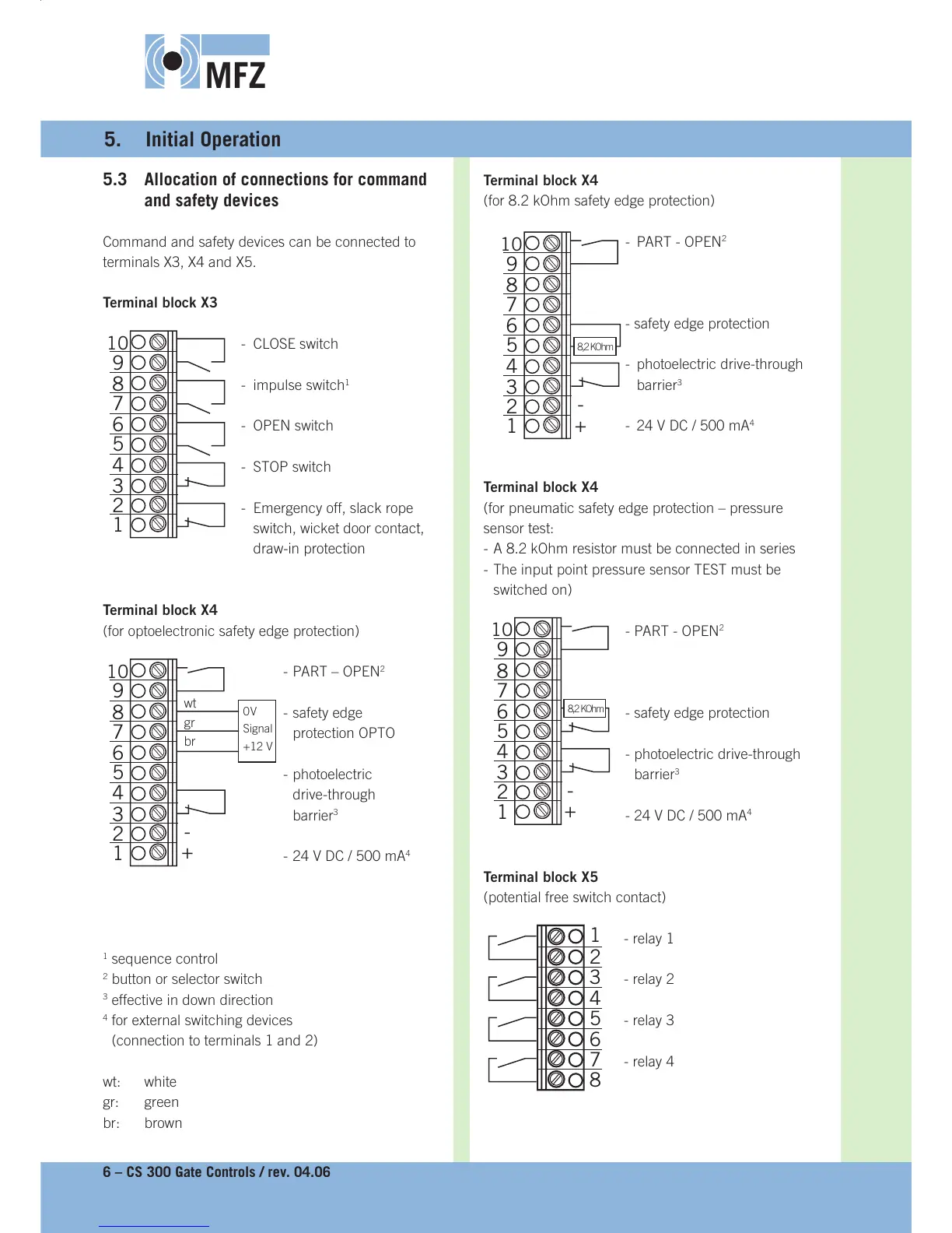
5.3 Allocation of connections for command
and safety devices
Command and safety devices can be connected to
terminals X3, X4 and X5.
Terminal block X3
- CLOSE switch
- impulse switch
1
- OPEN switch
- STOP switch
- Emergency off, slack rope
switch, wicket door contact,
draw-in protection
Terminal block X4
(for optoelectronic safety edge protection)
- PART – OPEN
2
- safety edge
protection OPTO
- photoelectric
drive-through
barrier
3
- 24 V DC / 500 mA
4
1
sequence control
2
button or selector switch
3
effective in down direction
4
for external switching devices
(connection to terminals 1 and 2)
wt: white
gr: green
br: brown
Terminal block X4
(for 8.2 kOhm safety edge protection)
- PART - OPEN
2
- safety edge protection
- photoelectric drive-through
barrier
3
- 24 V DC / 500 mA
4
Terminal block X4
(for pneumatic safety edge protection – pressure
sensor test:
- A 8.2 kOhm resistor must be connected in series
- The input point pressure sensor TEST must be
switched on)
- PART - OPEN
2
- safety edge protection
- photoelectric drive-through
barrier
3
- 24 V DC / 500 mA
4
Terminal block X5
(potential free switch contact)
- relay 1
- relay 2
- relay 3
- relay 4
1
2
3
4
5
6
7
8
1
2
3
4
5
6
7
8
9
10
1
2
3
4
5
6
7
8
9
10
+
-
wt
gr
br
0 V
Signal
+12 V
1
2
3
4
5
6
7
8
9
10
+
-
8,2 KOhm
1
2
3
4
5
6
7
8
9
10
+
-
8,2 KOhm