Blaze EMS-2 Operating Manual Page 51
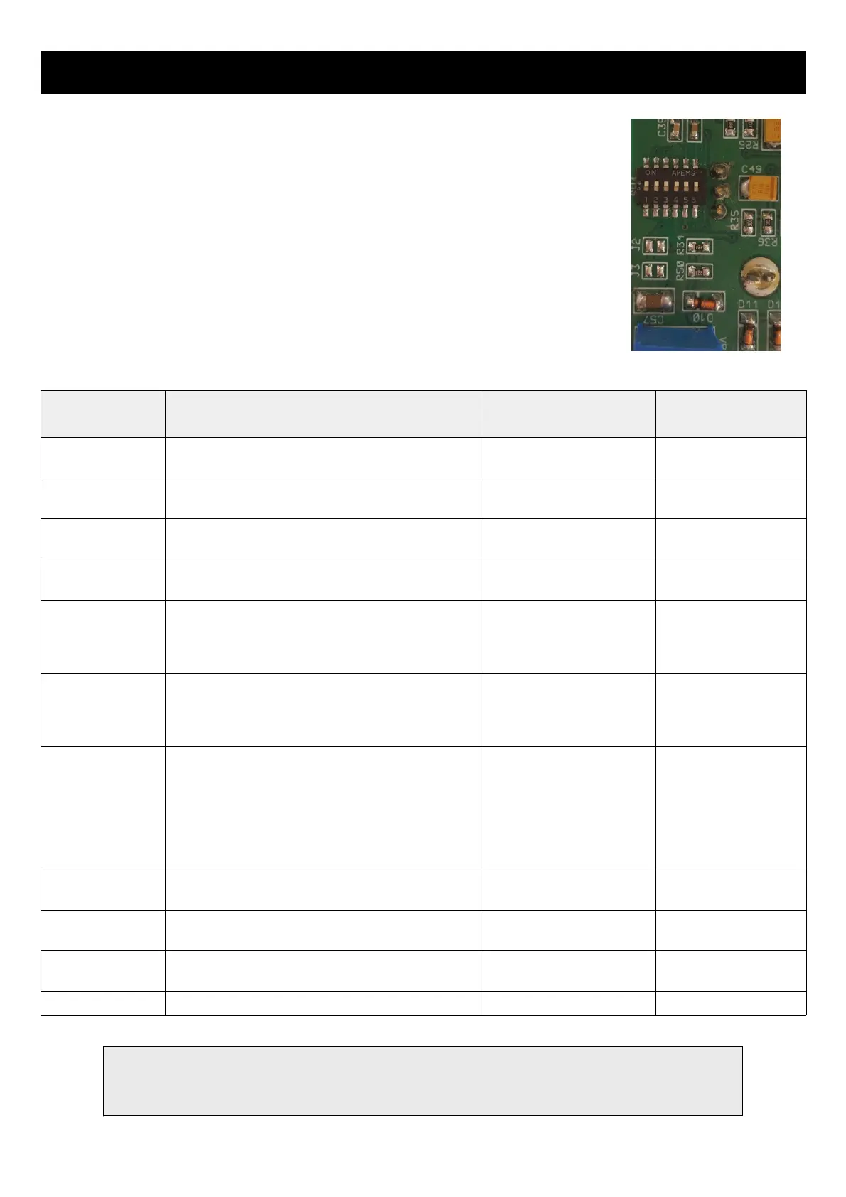
10.3.2 RPM Input Dipswitch settings
Setting dipswitch 5 to the “ON” position (default) enables a high frequency filter in the RPM 1
signal path.
Setting dipswitch 6 to the “ON” position (default) enables a high frequency filter in the RPM 2
signal path.
Some installations (direct coupling to a Magneto device for example) will require this to be
switched “OFF”. Dipswitch 1 is the closest switch to the edge of the PCB.
10.3.3 Engine RPM connection guide
Engine Connection / Sensor Pulses per
revolution
220 Ohm Ballast
resistor
Rotax 447 Connect the grey wire from the engine to the
RPM input
6 Certain installations,
see note below
Rotax 503 Connect the grey wire from the engine to the
RPM input
6 Certain installations,
see note below
Rotax 582 Connect the grey wire from the engine to the
RPM input
6 Certain installations,
see note below
Rotax 618 Connect the grey wire from the engine to the
RPM input
6 Certain installations,
see note below
Rotax 912 (S) Connect the rev counter wires (blue/yellow and
white/yellow). One of the two wires needs to be
connected to ground (engine block) and the
other to the RPM input.
1 Insert ballast resistor
Rotax 914 Connect the rev counter wires (blue/yellow and
white/yellow). One of the two wires needs to be
connected to ground (engine block) and the
other to the RPM input.
1 Insert ballast resistor
Engines with
magnetos
UMA Tach Sensor
T1A9-1 (Slick)
T1A9-2 (Bendix)
Connect the red or orange/white wire to 12V, the
black or blue/white and braid to ground. Connect
the white (signal) to the RPM input
1 pulse per revolution on
4-cylinder, 2 pole
magnetos
1.5 pulses per revolution
on 6-cylinder, 2 pole
magnetos
Certain installations
HKS engine Connect the orange wire from the CDI unit to the
RPM input
1 no
MTH engine Connect the green wire from ignition sensor to
the RPM input
2 no
Werner engine Connect the yellow wire from ignition sensor to
the RPM input
2 no
UL Power Connect the ECU pin 9 to the RPM input 2 no


 To Next Page