RC2 3
Power Supply
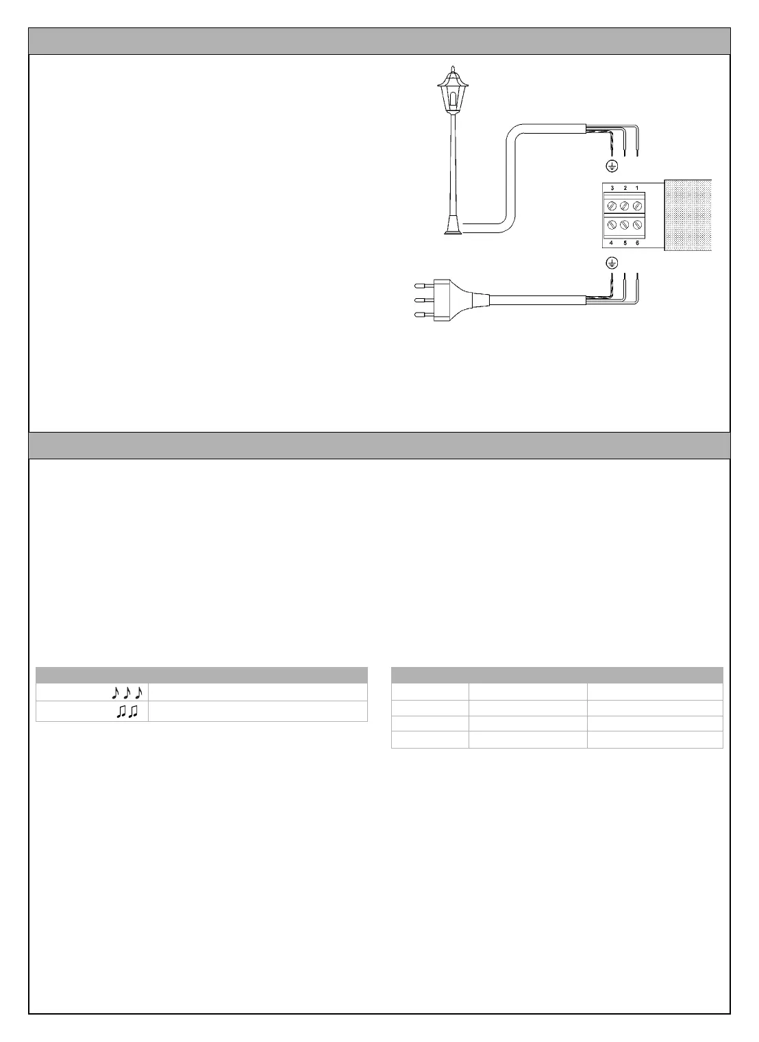
Use terminals 5-6-7 for the main power supply to the receiver
(ground, phase, neutral), as shown in figure 8 “Electrical Connec-
tions”
Connection to the Equipment to Be Controlled
The equipment to be controlled (Max 500W) must be connected to
terminals 1-2; No. 3 is the ground terminal.
WARNING
Terminal 7 (Neutral) is directly connected to terminal 2 of the
equipment to be controlled, which is therefore not com-
pletely isolated from the power supply line.
Carefully follow all the connection instructions. If you have any
doubts do NOT make experiments but refer to the relevant techni-
cal specifications.
Improper connection may cause serious damage to the
receiver.
4 Electrical Connections
Fig. 8
A memorization procedure must be executed in order to enable the
transmitter to control the receiver.
WARNING:
• All the memorization sequences described in this chapter are
timed, therefore they must be performed within the set time lim-
its.
• All the receivers that are within the range of the transmitter can
be memorized via radio; it is therefore expedient to power only
the receiver involved in the operation.
You can check whether any transmitters have been previously
memorized in the receiver; this is done by counting the number of
beeps emitted when the receiver is switched on.
Two different procedures can be followed to memorize the trans-
mitters:
- Mode I: simplified memorization (the transmitter keys are auto-
matically configured by the RC2 receiver)
- Mode II: advanced memorization (each single transmitter key
can be configured for a specific command)
Mode I (simplified memorization)
In this mode the functions of the transmitter keys are pre-set. The
keys are associated by pairs: keys 1 and 2 can perform the On-
Off commands from an RC2 receiver, whereas keys 3 and 4 can
perform the On-Off commands from a different RC2 receiver, as
shown in the example below.
When the memory is empty (no memorized transmitters) you can
proceed to program the first transmitter in Mode I as shown in table
[A].
WARNING: if you press key 1 or 2, this pair of keys will be mem-
orized, whereas if you press key 3 or 4, this latter pair of keys will
be memorized.
5 Memorizing the transmitters
Checking the memorized transmitters
3 short beeps Vi sono già dei trasmettitori memorizzati
2 long beeps Empty memory (no memorized transmitters)
Example of memorization in Mode I
Key 1 On on RC2 n.1
Key 2 Off on RC2 n.1
Key 3 On on RC2 n.2
Key 4 Off on RC2 n.2
RC2 IST 161 4858 Rev 00 3-06-2004 9:13 Pagina 3