14
68D5301
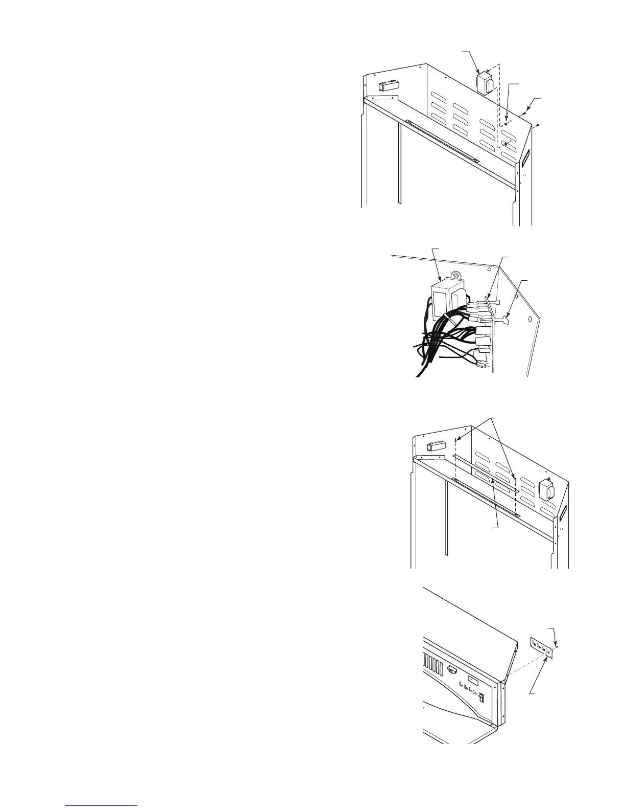
• Replacing Transformer
1. Follow Steps 1 through 3 in 'Replacing Heater/Blower'.
. Disconnect transformer wires from control board.
3. Remove screws and nuts from rebox surround to remove
transformer. Figure 17
4. Remove and discard transformer.
5. Place new transformer against inside of rebox surround and
replace screws and nuts removed in Step 3.
6. Reconnect transformer wires to control board. Refer to Wiring
Diagram, Figure 15 or 16.
7. Replace glass with brackets, and top panel.
8. Replace trim.
• Replacing Main Control Board
1. Follow Steps 1 through 3 in 'Replacing Heater/Blower'.
. Disconnect wires to main control board.
3. Squeeze top of standoffs to remove main control board and discard.
4. Gently push new control board onto standoffs to install.
5. Reconnect wires to main control board. Refer to Wiring Diagram,
Figure 15 or 16.
6. Replace glass with brackets and top panel.
7. Replace trim.
• Replacing Backlight LED Strip
1. Follow Steps 1 and 3 in 'Replacing Heater/Blower'.
. Disconnect wires from main control board.
3. Squeeze top of standoffs to remove backlight LED strip and discard.
4. Place new backlight LED strip onto standoffs and push gently.
5. Connect wires to main control board. Refer to Wiring Diagram, Figure 15
or 16.
6. Replace glass with brackets and top panel.
• Replacing Settings Control Board
1. Follow Steps 1 through 3 in 'Replacing Heater/Blower'.
. Disconnect wires from main control board.
3. Remove screws from bracket to remove settings control board.
4. Place new settings control board into position making sure each control
is aligned with slot in panel. Install using screws from Step 3. DO NOT
overtighten. This will damage control board.
5. Reconnect wires to main control board. Refer to Wiring Diagram, Figure
15 or 16.
6. Replace glass with brackets and top panel.
7. Replace trim.
Transformer
Nuts
Screws
FP400
Figure 17
FP2401
remove control board
Transformer
Main Control
Board
Standoffs
FP401
Figure 18
FP2402
replace backlight LED
Backlight
LED Strip
Standoffs
Figure 19
FP40
FP2403
replace settings cb
Screws
Settings
Control
Board
FP403
Figure 20