68D5301
7
• Framing
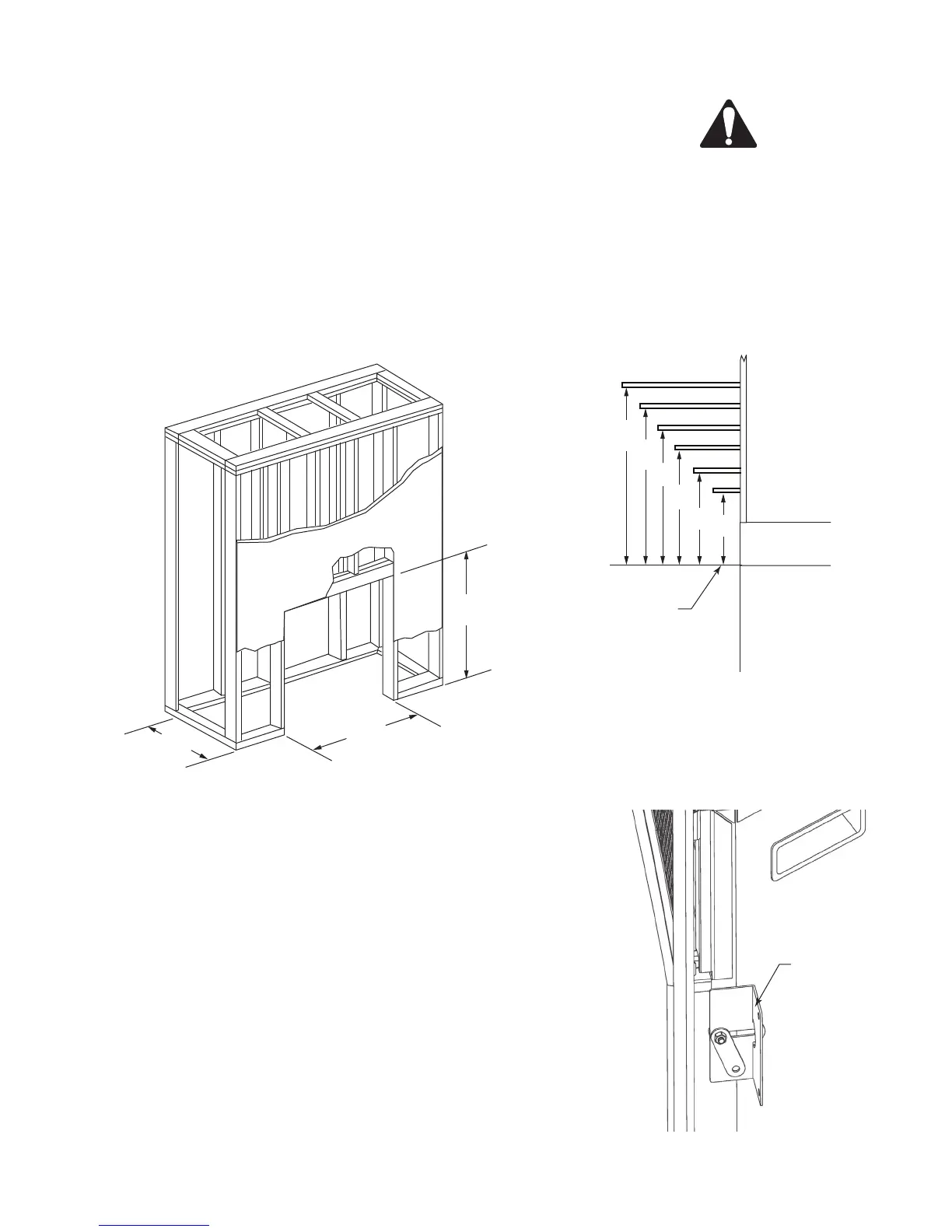
Figure 4 shows a typical framing of the heater using combustible materials. All
required clearances to combustibles must be adhered to. Header height is measured
from the base of the heater.
Tools and building supplies required for installation:
• Saw • Square
• Pliers • Gloves
• Hammer • Level
• Philips screwdriver • Surround
• Framing materials • Electric drill/bits
• Tape measure
• Wall-finishing materials
• Caulking material
1056O”
3456O”
3256O”
FP2570
framing
FP570
Figure 4
NOTE: The height that a com-
bustible mantel is tted above the
heater is dependent on the height
of the front selected. The minimum
height is 1" above the front.
CAUTION: Provide
adequate clear-
ances around the
air openings and adequate
accessibility clearances for
servicing and proper opera-
tions.
• Nailing Flange Installation
1. The replace has an adjustable nailing ange that will accommodate wall
installations from 1/" to 1Z\x" thick.
. Secure the nailing ange to the framing member. It is recommended to
remove the front face of the replace when nailing the ange to the wall.
Refer to the cleaning and maintenance section.
3. The nailing ange can be adjusted front to back by loosening the screw
that secures the nailing ange to the replace. Do not remove the screw
completely.
Figure 5
FP2390
mantel depth
7”
856M”
6”
12”
8”
6”
256O”
10"
4”
956O”
106M”
11”
FP390
Top of Fireplace
Opening
Adjustable
Nailing Flange
FP571