Mach 1, 3, 3+, 10, 15
4
©2018 Micro-Air Rev 1.01
Mach 1, 3, 3+, 10, 15 high profile models
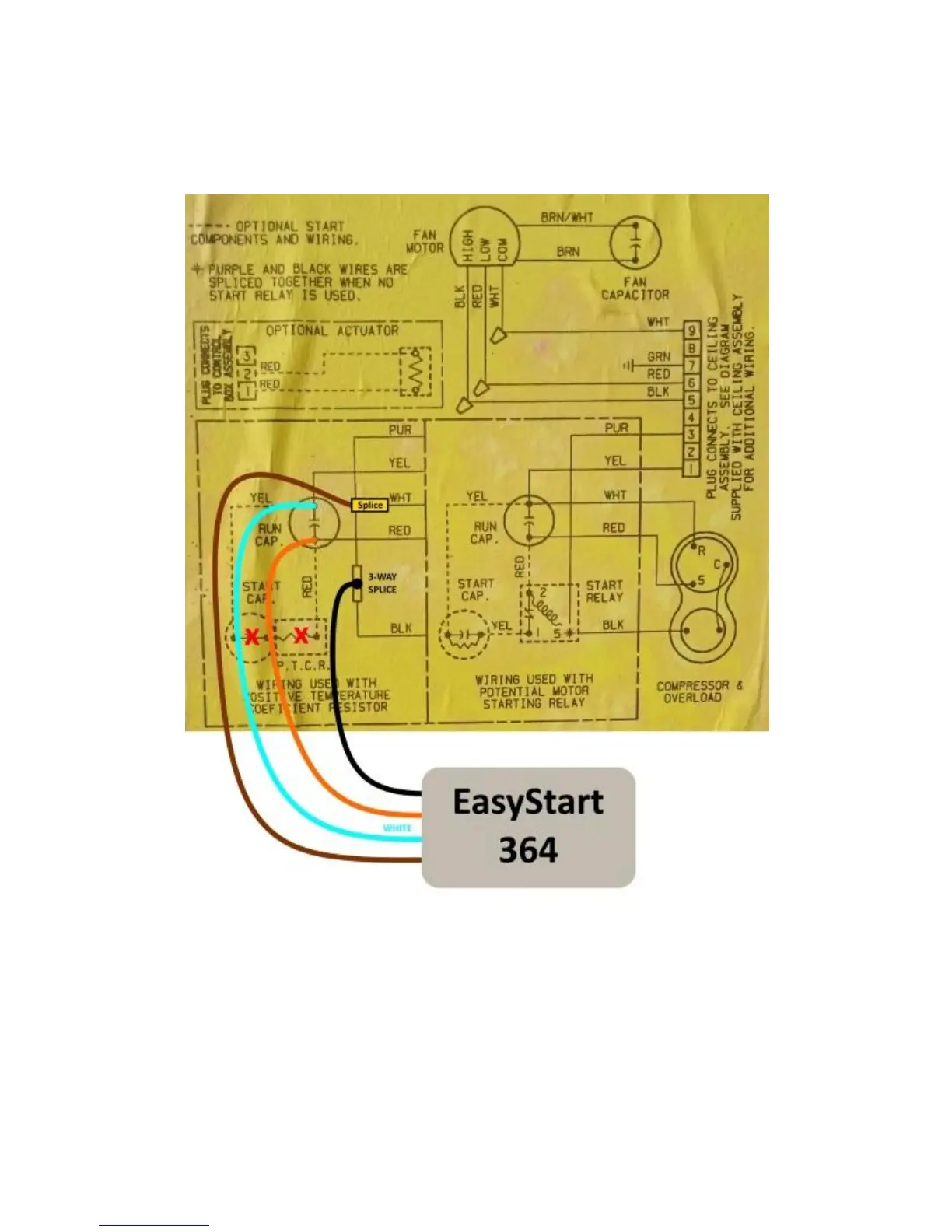
Wiring diagram
A Coleman AC may be factory configured four different ways as shown in the factory diagram
above. The dash outlined block on the left where EasyStart is connected shows a PTCR and start
capacitor. The right dashed block shows a start relay configuration. The dashed components inside each
block show that those components may not be installed in either configuration. There may be 2 or 3
capacitors inside of the electric box.
EasyStart installs the same way regardless of the configuration used in your air conditioner.
Follow the instructions in this manual to correctly install EasyStart.