Introduction
2020 Microchip Technology Inc. DS50002927A-page 11
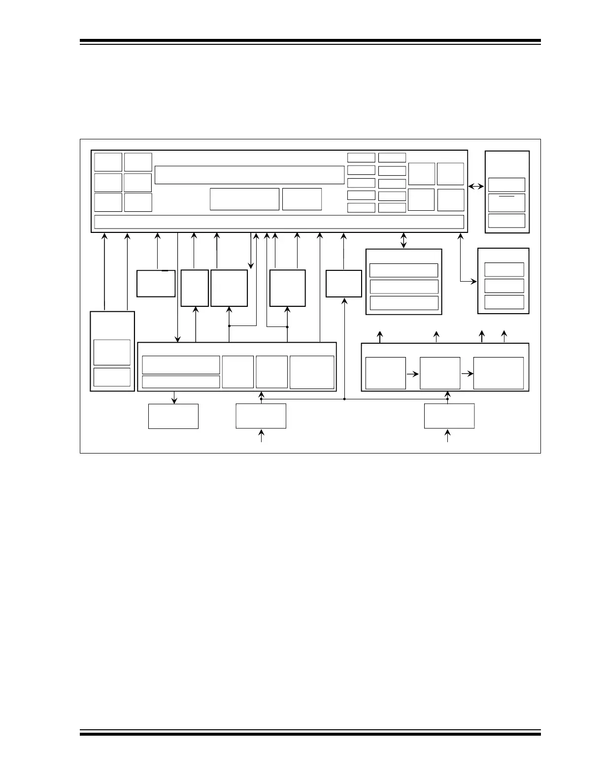
1.3 BLOCK DIAGRAM
The block diagram of the dsPIC33CK Low-Voltage Motor Control Board is shown in
Figure 1-2. For more information on electrical specifications, refer to
Appendix B. “Electrical Specifications”.
FIGURE 1-2: THE MOTOR CONTROL BOARD BLOCK DIAGRAM
Program/
User Interface
Push Buttons
LEDs
Potentiometer
+3.3V
Auxiliary Power Supply
+12V Output
DC-DC
Converter
(MIC28511)
+5V Output
DC-DC
Converter
(MCP16301)
+3.3V Output
LDO
(MCP1826)
+12V +5V
+3.3 VA
Three-Phase Inverter
MOSFET Temperature
J14
Connector
J2
Connector
J1
Connector
12-24 V
, 2.5A
PKOB V4
MCLR
Push Button
ICSP Header
MIC4605 x 3
Half-Bridge MOSFET Drivers
Three-Phase Inverter Bridge
Phase
Shunts
MCP9700
Temp Sensor
for Thermal
Protection
Bus
Speed/
Position
Feedbacks
Quadrature
Encoder
Interface
Hall Sensor
Interface
Quadrature Encoder
Feedbacks
Hall Sensor Feedbacks
dsPIC33CK256MP508
Reset
Control
I/O Control – Analog, Digital, Pull-up, Pull -Down, Remappable, Change Notification
ICSP™
Debug
UART
SCCP
DAC/
Comparators
QEI
Timer1
ADC – 2 x Dedicated Core and Shared Core
Op Amps
Clock
SPI
I
C
CAN FD
SENT
DMT
CRC
PMP
WDT
DMA
PWMs
External
Interface
TEMP
EXT
MCP6024
Op Amps for
Phase
Currents
Amplification
MCP651
Bus Current
Amplification
Phase
Phase
Volta
es
V
V
V
In
ut DC Volta
e
DC Voltage
Scaling
Circuit
V
Other Interfaces
MCP2200
USB to UART Converter