2020 Microchip Technology Inc. DS50002927A-page 57
dsPIC33CK LOW-VOLTAGE
MOTOR CONTROL BOARD
USER’S GUIDE
Appendix C. Design Details
C.1 INTRODUCTION
This chapter provides design details of the:
• Current Amplifier Circuits
• Auxiliary Power Supply
C.2 CURRENT AMPLIFIER CIRCUITS
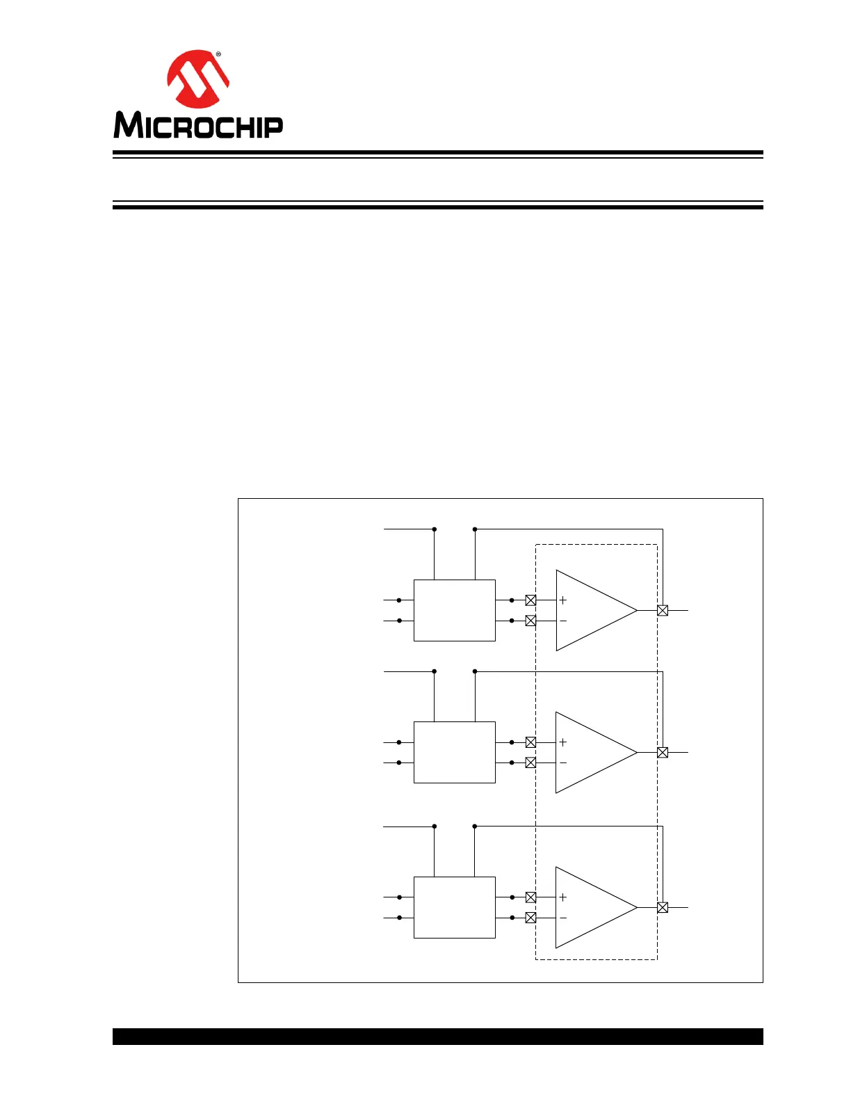
Circuits used for amplifying motor phase currents and DC bus current using internal
amplifiers of the dsPIC33CK256MP508 are shown in Figure C-1. Circuits used for
amplifying motor phase currents and DC bus current using external amplifiers U5-A,
U5-B, U5-C and U15 are shown in Figure C-2. The detailed schematics of the block
“Filter, Feedback and Bias Circuit” used in Figure C-1 and Figure C-2 are shown in
Figure C-3.
FIGURE C-1: dsPIC
®
DSC INTERNAL AMPLIFIERS
Filter,
Feedback and
Bias Circuit
Filter,
Feedback and
Bias Circuit
Filter,
Feedback and
Bias Circuit
dsPIC33CK256MP508
IB
IA
IBUS
VREF
VREF
VREF
SHUNT_IBUS_N
SHUNT_IBUS_P
SHUNT_IB_N
SHUNT_IB_P
SHUNT_IA_N
SHUNT_IA_P
Op Amp 2
Op Amp 1
A
B
D
E
16
F
F
20
18
41
45
43
23
29
28
Op Amp 3