2020 Microchip Technology Inc. DS50002927A-page 29
dsPIC33CK LOW-VOLTAGE
MOTOR CONTROL BOARD
USER’S GUIDE
Chapter 3. Hardware Description
3.1 INTRODUCTION
This chapter provides a detailed description of the hardware features of the
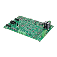
dsPIC33CK Low-Voltage Motor Control Board. The Motor Control Board is intended to
demonstrate the capability of the dsPIC33CK family of single core Digital Signal
Controllers (DSCs) for motor control applications.
The motor control inverter on the Motor Control Board is controlled by the highest pin
count variant dsPIC33CK256MP508 device from the dsPIC33CK family. The Motor
Control Board incorporates a Hall sensor/Quadrature Encoder Interface (QEI), and
sensing circuits to measure DC voltage, phase voltages, bus current and phase
currents, etc. In addition, a USB-UART interface, mikroBUS™ sockets and a PICkit™
On-Board (PKOB) programmer/debugger circuit are provided.
The motor control inverter can be operated by using an input voltage in the range of
12V to 48V and can deliver a continuous output phase current of 10A (RMS) in the
specified operating range. For more information on electrical specifications, see
Appendix B. “Electrical Specifications”.
3.2 HARDWARE SECTIONS
This chapter covers the following hardware sections of the dsPIC33CK Low-Voltage
Motor Control Board:
• dsPIC33CK256MP508 and Auxiliary Circuits
• Power Supply
• Three-Phase Inverter Bridge
• Current Sensing Circuits
• Voltage Sensing Circuit
• Hall Sensor/Quadrature Encoder Interface
• External Temperature Sensor Interface
• User Interface
• Debug Serial UART Interface
• mikroBUS™ Sockets
• Programmer/Debugger Interface
Figure 3-1 and Ta ble 3 - 1 describe the hardware sections of the Motor Control Board.

 Loading...