Hardware Description
2020 Microchip Technology Inc. DS50002927A-page 37
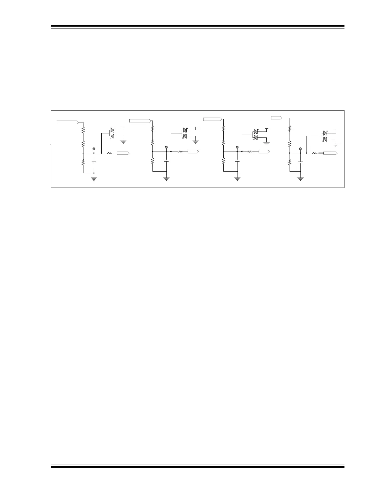
3.2.5 Voltage Sensing Circuit
A voltage sensing network is provided to scale down the DC supply voltage powering
the inverter to connect it to an analog channel of the dsPIC DSC for voltage measure-
ment. The voltage divider network, formed by resistors, R69, R77 and R87, divides the
DC input voltage (V
DC) at a voltage scaling ratio of 1:21.6 (see Figure 3-5). The scaled
DC input voltage (V_BUS) is connected to the analog input pin of the dsPIC DSC for
measurement.
FIGURE 3-5: VOLTAGE SENSING CIRCUIT
The Motor Control Board can also be to used to run BLDC motors with a trapezoidal
commutation scheme by monitoring back-EMF signals. For such an application, the
motor back-EMF is scaled down by voltage dividers before they are applied to the
analog channels of the dsPIC DSC. The filter capacitors are provided to filter the noise.
The voltage divider network divides phase voltages (PHASE_A, PHASE_B and
PHASE_C) at a voltage scaling ratio of 1:21.6 (see Figure 3-5). The scaled back-EMF
signals (V_A, V_B and V_C) are connected to analog input pins of the dsPIC DSC.
In case of any voltage transients, kickbacks or resistor failures, the clamping diodes are
provided at the scaled voltage outputs to ensure the voltages at the analog inputs do
not exceed the voltage limits of the dsPIC DSC inputs.
3.2.6 Hall Sensor/Quadrature Encoder Interface
The Motor Control Board can also be used to run PMSM/BLDC motor control
applications using the Hall sensor/Quadrature Encoder to determine rotor position and
speed. The connectors, J7and J8, are provided to interface Hall sensor feedback and
encoder feedback, respectively, with the Motor Control Board. The Hall sensor and
Quadrature Encoder Interface circuit supports either open-collector or push-pull
output sensors.
The Hall sensors and Quadrature Encoder can be powered by the +5V supply or +3.3V
supply available through the interface connector terminals. A capacitor is added to
each signal output to reduce the noise. The voltage divider can be configured to scale
down the sensor signal, from a +5V level to a +3.3V level, when push-pull output
sensors are powered by a +5V supply. For circuit details, refer to Figure A-6 in
Appendix A. “Schematics and Layout”.
The connector J7 and J8 pinouts are summarized in Section 2.2.4 “Hall Sensor
Interface Connector (J7)” and Section 2.2.5 “Quadrature Encoder Interface
Connector (J8)”.
T
VBUS
301R
R83
V_BUS
DC Bus Voltage
VDC
3.3k
R87
0.1 μF
C52
V_A
V_B
PHASE_A
PHASE_B
V_C
PHASE_C
3.3k
R86
VB
301R
R82
3.3k
R84
VC
301R
R80
VA
301R
R81
3.3k
R85
1
2
3
BAS40-04
D6
1
2
3
BAS40-04
D5
1
2
3
BAS40-04
D4
1
2
3
BAS40-04
D7
AGND AGND AGND AGND
AGND
AGND
AGNDAGND
34k
R76
34k
R73
34k
R74
34k
R77
34k
R69
34k
R68
34k
R67
34k
R70
+3.3VA +3.3 VA
+3.3 VA
+3.3 VA
1000 pF
C51
1000 pF
C49
1000 pF
C50