Board Interface Description
2020 Microchip Technology Inc. DS50002927A-page 17
2.2.5 Quadrature Encoder Interface Connector (J8)
Quadrature Encoders are used to detect the rotor position and speed of the motor.
Connector J8 can be used to interface the encoder outputs with the Motor Control
Board, enabling sensor-based BLDC/PMSM motor control applications. Ta b le 2 - 7
shows the pin description of connector J8. The connector provides two supply outputs,
+5V and +3.3V, which can be used as input supplies to the Quadrature Encoder based
on the encoder specification.
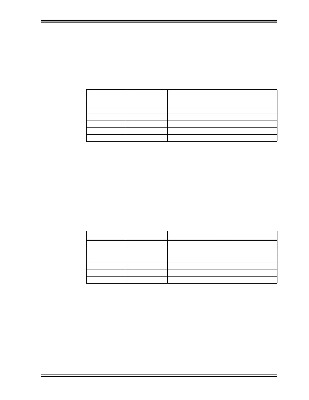
TABLE 2-7: PIN DESCRIPTION – CONNECTOR J8
2.2.6 External Temperature Sensor Interface Connector (J9)
The 2-pin connector (2.5 mm pitch) J9 can be used for interfacing a thermistor to the
board. This is not populated by default. When needed, populate the connector with
Part Number B2B-EH-A(LF)(SN) or similar.
2.2.7 ICSP™ Header for Programmer/Debugger Interface (J10)
The 6-pin header J10 can be used for connecting the programmer/debugger, for
example, PICkit™ 3, for programming and debugging the dsPIC33CK256MP508.
This is not populated by default. When needed, populate the connector with
Part Number 68016-106HLF or similar. The pin details are provided in Table 2-8.
TABLE 2-8: PIN DESCRIPTION – CONNECTOR J10
Pin # Signal Name Pin Description
1 +5V +5V Supply to Quadrature Encoder
2 +3.3V +3.3V Supply to Quadrature Encoder
3 DGND Digital Ground
4 QEA Quadrature Encoder Phase A Feedback of the Motor
5 QEB Quadrature Encoder Phase B Feedback of the Motor
6 INDX Quadrature Encoder INDEX Feedback of the Motor
Pin # Signal Name Pin Description
1MCLR
Device Master Clear (MCLR)
2DVDD Digital Supply Voltage
3 DGND Digital Ground
4 PGD Device Programming Data Line (PGD)
5 PGC Device Programming Clock Line (PGC)
6 No Connection —