dsPIC33CK Low-Voltage Motor Control Board User’s Guide
DS50002927A-page 18 2020 Microchip Technology Inc.
2.2.8 mikroBUS™ Sockets for Interfacing a Click Board™ (J11, J12)
Two mikroBUS sockets are provided on the Motor Control Board which can be used to
expand the functionality by attaching an add-on board, called a ‘Click Board’. The
mikroBUS sockets, J11 and J12, are labeled as ‘A’ and ‘B’, respectively. The
Motor Control Board implements the mikroBUS socket pinouts, as specified in the
“mikroBUS™ Standard Specifications v2.0” (refer to www.mikroe.com/mikrobus).
The pinout consists of three groups of communication pins (SPI, UART and I
2
C), six
additional pins (PWM, interrupt, analog input, Reset and chip select) and two power
groups (+3.3V-GND and 5V-GND).
For pin mapping information between the dsPIC DSC and the mikroBUS sockets, refer
to the schematics in Section A.1 “Board Schematics and Layout” or
Section 2.4 “Pin Functions of the dsPIC DSC”.
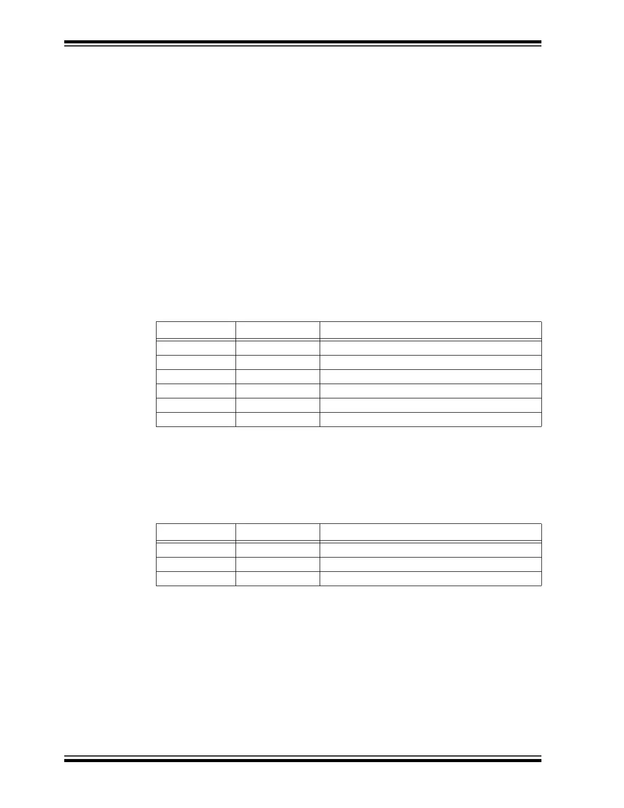
2.2.9 USB Connector for PKOB Interface (J13)
This is a standard female USB Micro-B connector that provides USB communication
when interfacing with the PICkit On-Board (PKOB) programming/debugging tool. Pin
assignments for connector J13 are shown in Ta b le 2-9.
TABLE 2-9: PIN DESCRIPTION – CONNECTOR J13
2.2.10 Inverter Output Connector (J14)
The Motor Control Board can drive a three-phase PMSM/BLDC motor. Motor control
inverter outputs are available on connector J14. Pin assignments for connector J14 are
shown in Ta ble 2 - 1 0 .
TABLE 2-10: PIN DESCRIPTION – CONNECTOR J14
Pin # Signal Name Pin Description
0 No Connection Body is Connected to GND
1VBUS USB 5V
2 D_N USB Data-
3 D_P USB Data+
4 No Connection —
5 GND PKOB Ground (GND)
Pin # Signal Name Pin Description
1 PHASE C Phase 3 Output of Inverter
2 PHASE B Phase 2 Output of Inverter
3 PHASE A Phase 1 Output of Inverter