Board Interface Description
2020 Microchip Technology Inc. DS50002927A-page 25
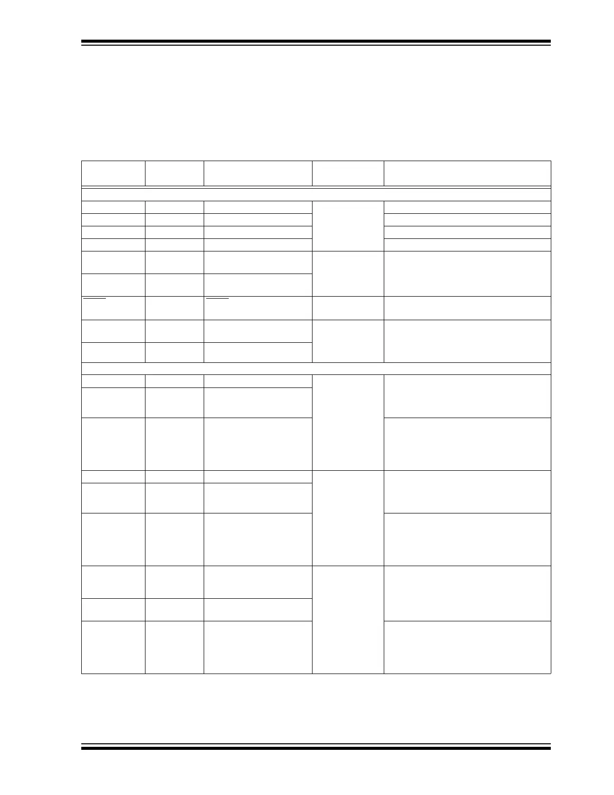
2.4 PIN FUNCTIONS OF THE dsPIC DSC
The on-board dsPIC33CK256MP508 device (see U9 in Figure A-2) enables the control
of various features of the Motor Control Board through its peripherals and CPU
capability. Pin functions of the dsPIC DSC are grouped according to their functionality
and presented in Ta b le 2- 14.
TABLE 2-14: dsPIC
®
DSC PIN FUNCTIONS
Signal
dsPIC
®
DSC
Pin #
dsPIC DSC Pin Function
dsPIC DSC
Peripheral
Remarks
dsPIC DSC Configuration – Supply, Reset, Clock and Programming
+3.3V 12, 31, 51, 71 V
DD
Supply +3.3V digital supply to dsPIC DSC
DGND 11, 32, 50, 70 V
SS
Digital ground
+3.3VA 25 AV
DD
+3.3V analog supply to dsPIC DSC
AGND 26 AV
SS
Analog Ground
OSCI 34 OSCI/CLKI/AN5/RP32/
PMD10/PMA10/RB0
Oscillator with PLL Connects to crystal (X2) on the board
OSCO 35 OSCO/CLKO/AN6/RP33/
PMA1/PMALH/PSA1/RB1
MCLR
9MCLR Reset Connects to a push button (SW4), ICSP™
header (J10) and PKOB circuit
PGD 55 PGD3/RP37/SDA2/PMA14/
PMCS1/PSCS/RB5
In-Circuit Serial
Programming™
(ICSP™) or
In-Circuit Debugger
Connects to ICSP header (J10) and
PKOB programming/debugging tool
PGC 56 PGC3/RP38/SCL2/RB6
dsPIC DSC Internal Amplifier Connections for Current Amplification
SHUNT_IA_P 20 OA1IN+/AN9/PMA6/RA2 Operational
Amplifier 1
(Op Amp #1) and
Dedicated ADC
Core #0
Differential current feedback from shunt
resistor Rsh1 connects to noninverting and
inverting inputs of Op Amp #1 through input
resistors
SHUNT_IA_N 18 OA1IN-/ANA1/RA1
IA 16 OA1OUT/AN0/CMP1A/
IBIAS0/RA0
Op Amp #1 output, which is amplified Phase A
current. For the output to be available, config-
ure and enable Op Amp #1, populate the
resistor R125 (0R) in the amplifier feedback
and remove R121 if populated
SHUNT_IB_P 45 PGC2/OA2IN+/RP36/RB4 Operational
Amplifier 2
(Op Amp #2) and
Dedicated ADC
Core #1
Differential current feedback from shunt
resistor Rsh2 connects to noninverting and
inverting inputs of Op Amp #2 through input
resistors
SHUNT_IB_N 43 PGD2/OA2IN-/AN8/RP35/
RB3
IB 41 OA2OUT/AN1/AN7/ANA0/
CMP1D/CMP2D/CMP3D/
RP34/SCL3/INT0/RB2
Op Amp #2 output, which is amplified Phase B
current. For the output to be available, config-
ure and enable Op Amp #2, populate the
resistor R133 (0R) in the amplifier feedback
and remove R129 if populated
SHUNT_IBUS_P 29 OA3IN+/AN14/CMP2B/
ISRC1/RP50/PMD13/
PMA13/RC2
Operational
Amplifier 3
(Op Amp #3) and
Shared ADC Core
Differential current feedback from shunt
resistor Rsh4 connects to noninverting and
inverting inputs of Op Amp #3 through input
resistors
SHUNT_IBUS_N 28 OA3IN-/AN13/CMP1B/
ISRC0/RP49/PMA7/RC1
I
BUS
23 OA3OUT/AN4/CMP3B/
IBIAS3/RA4
Op Amp #3 output, which is amplified bus
current. For the output to be available, config-
ure and enable Op Amp #3, populate the
resistor R141 (0R) in the amplifier feedback
and remove R137 if populated