2020 Microchip Technology Inc. DS50002927A-page 13
dsPIC33CK LOW-VOLTAGE
MOTOR CONTROL BOARD
USER’S GUIDE
Chapter 2. Board Interface Description
2.1 INTRODUCTION
This chapter provides a more detailed description of the input and output interfaces of the
dsPIC33CK Low-Voltage Motor Control Board. This chapter covers the following topics:
• Board Connectors
• User Interface Hardware
• Pin Functions of the dsPIC DSC
2.2 BOARD CONNECTORS
This section summarizes the connectors on the Motor Control Board. The connectors
are intended for:
• Supplying input power to the Motor Control Board
• Delivering inverter outputs to the motor
• Interfacing motor position sensors, such as Hall sensors or the Quadrature
Encoder
• Enabling the user to program/debug the dsPIC33CK256MP508 device
• Interfacing the Click Boards™
• Establishing communication with the host PC
• Interfacing the external temperature sensor (thermistor)
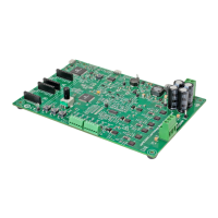
The connectors on the Motor Control Board are shown in Figure 2-1 and summarized
in Ta bl e 2- 1.

 Loading...