2016 Microchip Technology Inc. DS50002466A-page 25
2.4.24 SW,<hex8>,<hex8>
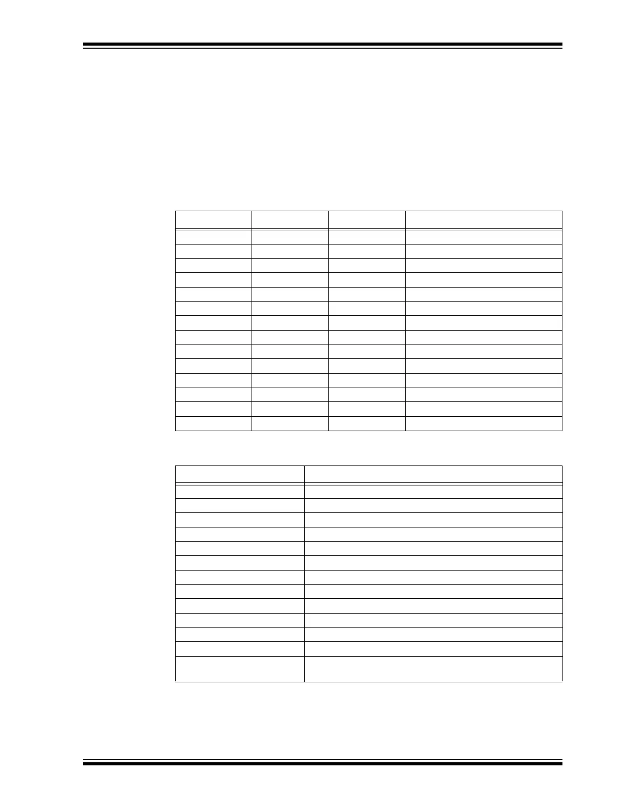
Command SW is used to configure pin functions. It expects two input parameters.
The first parameter is an 8-bit hex of the pin index. Tabl e 2-8 shows the pin indexes and
the corresponding RN4870/71 pins. Note that some pins apply only to RN4870, some
others to RN4870/71 and rest is available to both RN4870 and RN4870/71.
The second parameter is an 8-bit hex of function to be assigned to the pin. The
supported functions are listed in Table 2-9. For detailed description on system
functions, refer to “RN4870/71 Bluetooth
®
4.2 Low Energy Module Data Sheet”
(DS50002489A).
TABLE 2-8: PIN INDEX AND RN4870/71 PINS
Pin Index RN4870 Pins RN4871 Pins Default Function
00 P07 — Low Battery Indication
01 P10 — Status 2
02 P11 — Status 1
03 P22 — None
04 P24 — None
05 P31 — RSSI Indication
06 P32 — Link Drop
07 P33 — UART Rx Indication
08 P34 — Pairing
09 P35 — None
0A P12 P12 None
0B P13 P13 None
0C — P16 UART Rx Indication
0D — P17 None
TABLE 2-9: CONFIGURABLE FUNCTIONS
Function Index Function Description
00 None
01 Low Battery Indication
02 RSSI Indication
03 Link Drop
04 UART RX Indication
05 Pairing
06 RF Active Indication
07 Status 1
08 Status 2
09 Pin Trigger 1
0A Pin Trigger 2
0B Pin Trigger 3
0C UART Mode Switch: Rising edge for UART Transparent
mode; falling edge for Command mode.
Example: SW,03,06 // Assign Pin P22 to function RF Active Indication
Response: AOK
ERR
// Success
// Syntax error or invalid parameter