microHAM © 2010 All rights reserved
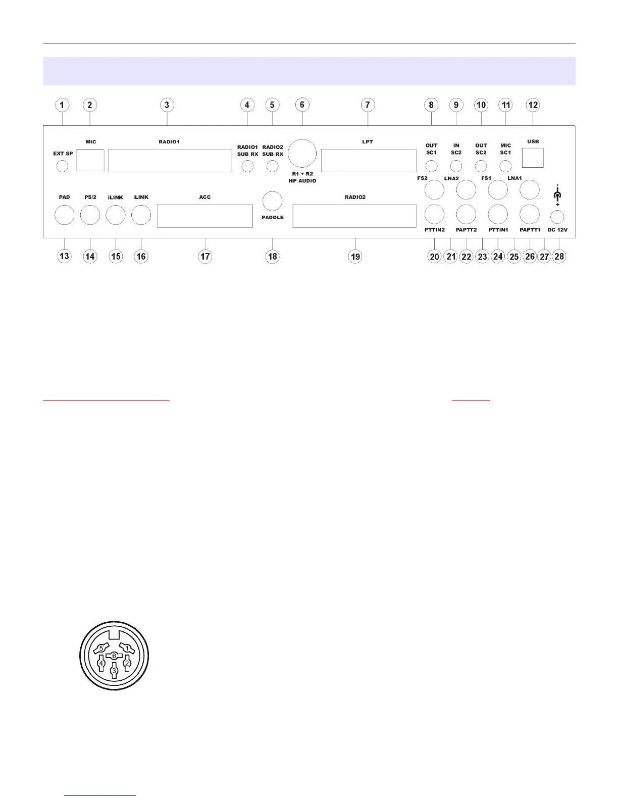
Rear Panel
(1) – EXT SP: External speaker or second headphones (in parallel with front panel).
Connector: 3.5mm (1/8”) stereo
TIP – Left channel RING – Right channel SHELL – Ground
(2) – MIC: Station microphone (original) for Radio #1.
Connector: RJ45 female. If the original radio microphone uses a connector other than an RJ45 the
appropriate adapter is provided with the cable set. All microphone controls are connected to the
RADIO1 DB37 connector (pins 12-15 and 30-33).
IMPORTANT WARNING: If dissimilar radios are attached to the MK2R or MK2R+. NEVER connect the
microphone from Radio #2 to this jack.
(3) – RADIO1: Multi-pin jack for RADIO1 interconnection.
Connector: DB37 female
Detailed description is in Appendix A.
(4) – RADIO1 SUB RX: Input for constant level audio from the second (SUB) receiver RADIO1.
Connector: 3.5mm (1/8”) stereo
TIP – Signal RING – Signal (internally connected to TIP) SHELL – Ground
(5) – RADIO2 SUB RX: Input for constant level audio from the second (SUB) receiver RADIO2.
Connector: 3.5mm (1/8”) stereo
TIP – Signal RING – Signal (internally connected to TIP) SHELL – Ground
(6) – R1 + R2 HP AUDIO: Input for headphone audio outputs from both RADIO1 and RADIO2.
Connector: DIN6
Pin 1 – RADIO1 Left channel (TIP)
Pin 2 – RADIO1 Right channel (RING)
Pin 3 – RADIO1 Ground (SHELL)
Pin 4 – RADIO2 Left channel (TIP)
Pin 5 – RADIO2 Right channel (RING)
Pin 6 – RADIO2 Ground (SHELL)
11