9
The DIP Switch SW10, is used to provide another four of the MPM inputs and also to select optional operational modes
for the MPM, refer to Figure 10.
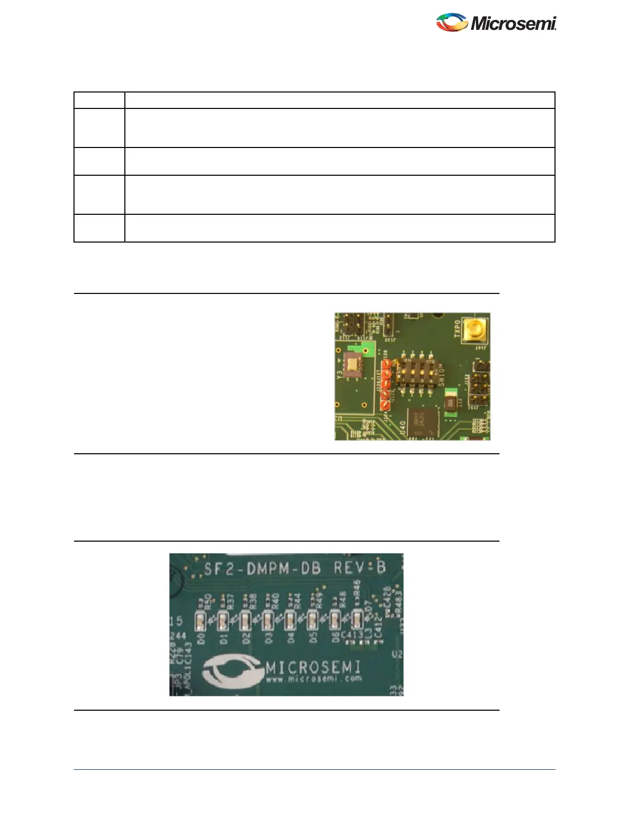
The eight LEDs on the DMPM Board display the state of the first eight MPM outputs, refer to Figure 11. With the default
configuration, these LEDs represent the state of the first eight APOLs. When an LED is ON, the corresponding APOL
is in a non-nominal state. When an LED is OFF, the corresponding APOL is in a non-nominal state. This is useful when
sequencing the APOLs, as you can adjust the POT for a channel until it enters the nominal state by watching for the
corresponding LED to turn off.
Table 4 • MPM Status Description
Status Description
Stopped Power-off sequencing is successful and the MPM is idle. None of the following are active: channel
threshold monitoring, output flag generation, and open or closed trimming. The channel voltages can be
read in any state.
Starting Executing power-on sequencing during which open-loop trimming (if applicable), channel threshold
monitoring, and output flag generation are active.
Started Power sequencing is successful; the MPM is now active and reading the channel voltages on-demand,
monitoring channel thresholds, executing closed-loop trimming (if applicable), and generating output
flags.
Stopping Executing power-off sequencing before closed-loop trimming (if applicable) is switched off but the
channel threshold monitoring and output flag generation remains operational.
Figure 10 • SF2-Dev-Kit SW10
Figure 11 • SF2-DMPM-DB LEDs
SW10.1 is connected to MPM input 5.
SW10.2 is connected to MPM input 6.
SW10.3 is connected to MPM input 7.
SW10.4 is connected to MPM input 8.