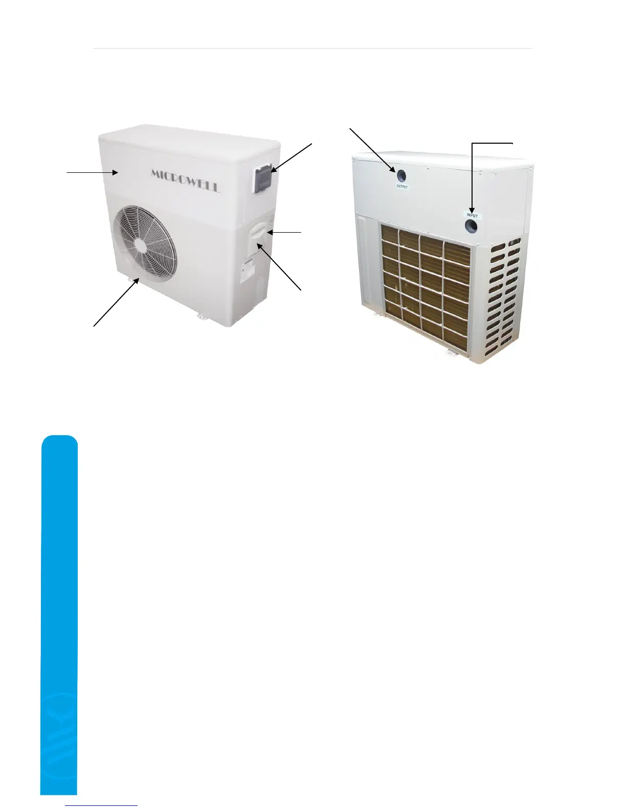
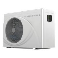
3.4 Description of the basic parts
Legend: 1
– Protecting grates of the fan (air outlet)
2 – Cover
3 – Control panel
4 – Valve for refilling the refrigerant (under the cover)
5 – Intake electric cable
6 – Water outlet connection hub
7 – Water inlet connection hub
3.5 Safety and control systems
The heat pump is equipped with the following systems:
Temperature based control of the heat pump operation:
The heat sensor placed on the heat exchanger, ensures switching off of the heat pump
when reaching the requested water temperature. The normal operating mode gets
renewed if the water temperature in the exchanger drops by 3 °C (manufacturing
setting) below the requested value.
Safety systems:
Water flow sensor placed on the heat exchanger inlet.
The water flow sensor switches on the heat pump when there is water flowing through
the heat pump exchanger, and switches it off when the water flow stops.
Sensor of the minimal and maximal gas pressure in the cooling circuit.
Heat sensor on the outlet from the compressor.
Pause time.
The unit is equipped with a switching time delaying device with a set 3 minutes delay period, for
protecting the control elements in the circuit and eliminating repeated restarts and contactor
vibrations.This time delay will automatically restart the unit cca. 3 minutes after every single
interruption of the heat pump operation. Even if there is only a short interruption of the power
supply, the pause time will get activated, so the unit can not start the operation earlier than the
2
1
3
5
4
6
7