Installation and user manual | 7
HEAT PUMP MICROWELL HP COMPACT
pressures in the cooling circuit of the heat pump get balanced. Interruption of the power supply
during the pause time does not influence the time interval.
If failure happens in any of these systems, there will be an error message shown on the display.
Please check chapter
7.4 Failure reports and their elimination in the manual.
Warning:
Elimination or disabling from operation of any of the control or safety system, results in
warranty cancellation.
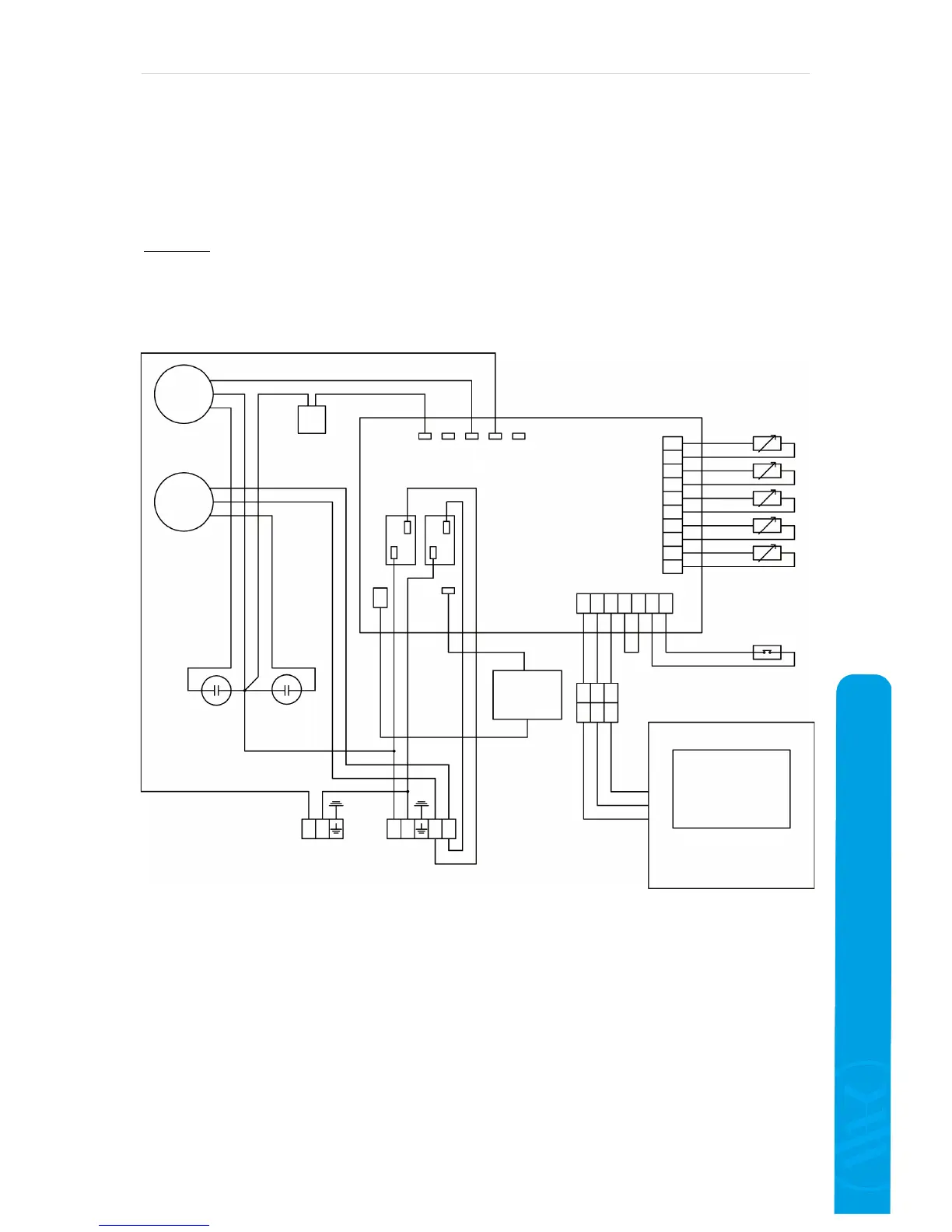
3.6 Block wiring diagram of the PCB board
Legend:
OUT 3 – output of 4-way valve
OUT 4 – output of 4-way valve
OUT 5 - fan
OUT 6 – water pump
OUT 7 – thermal protection
FM
CM
Fan