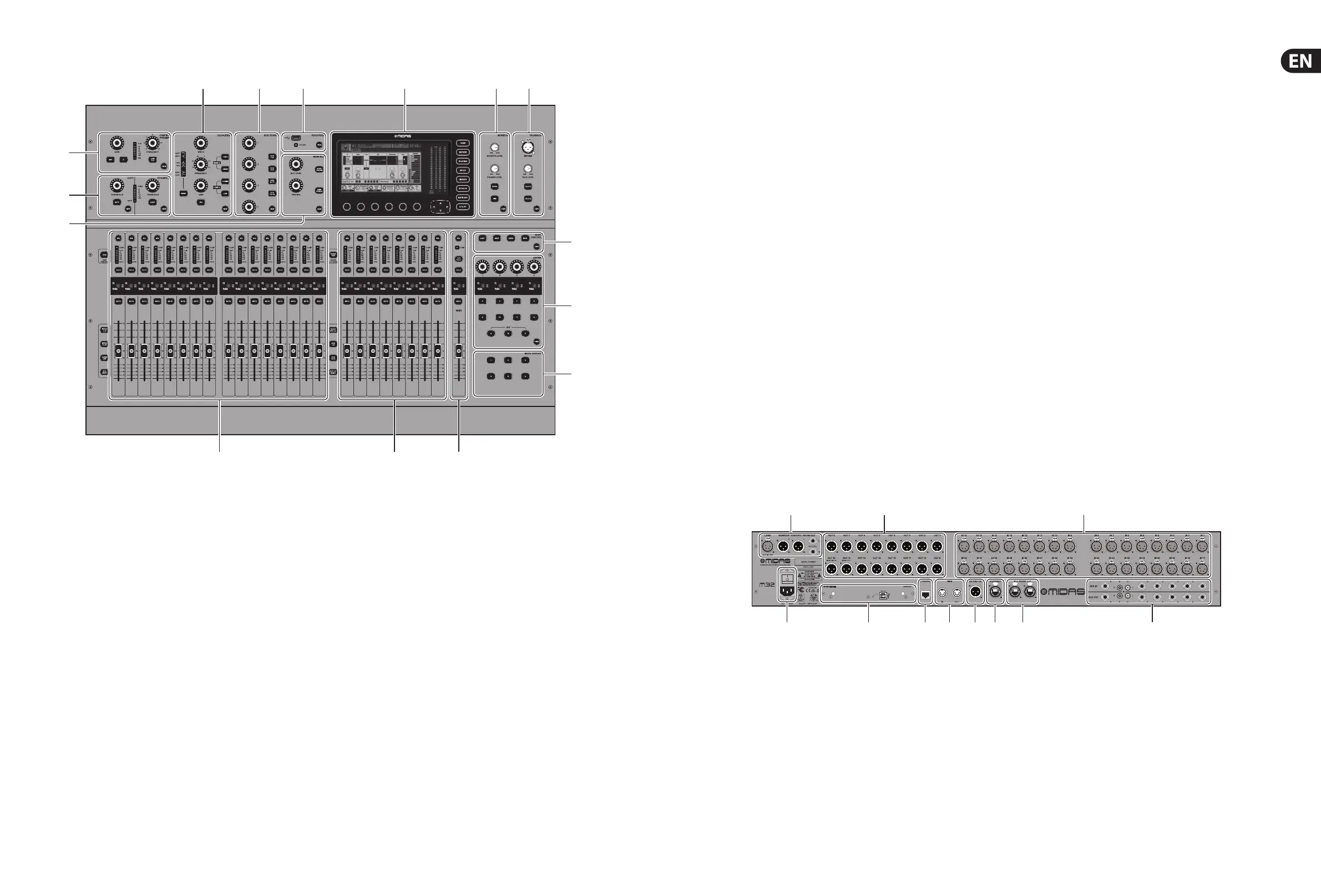
1. Control Surface
(1) CONFIG/PREAMP - Adjust the preamp gain
for the selected channel with the GAIN
rotary control. Press the 48 V button to apply
phantom power for use with condenser
microphones and press the Ø button to
reverse the channel’s phase. The LED meter
displays the selected channel’s level. Press the
LOW CUT button and select the desired
high-pass frequency to remove unwanted
lows. Press the VIEW button to access more
detailed parameters on the Main Display.
(2) GATE/DYNAMICS - Press the GATE button
to engage the noise gate and adjust the
threshold accordingly. Press the COMP button
to engage the compressor and adjust the
threshold accordingly. When the signal level
in the LCD meter drops below the selected
gate threshold , the noise gate will silence
the channel. When the signal level reaches
the selected dynamics threshold, the peaks
will be compressed. Press the VIEW button
to access more detailed parameters on the
MainDisplay.
(3) EQUALISER - Press the EQ button to
engage this section. Select one of the four
frequency bands with the LOW, LO MID,
HI MID and HIGH buttons. Press the MODE
button to cycle through the types of EQ
available. Boost or cut the selected frequency
with the GAIN rotary control. Select the
speci c frequency to be adjusted with the
FREQUENCY rotary control and adjust the
bandwidth of the selected frequency with the
WIDTH rotary control. Press the VIEW button
to access more detailed parameters on the
Main Display.
(4) BUS SENDS - Quickly adjust the bus sends by
selecting one of the four banks, followed by
one of the four rotary controls. Press the VIEW
button to access more detailed parameters on
the Main Display.
(5) RECORDER - Connect an external memory
stick to install rmware updates, load and
save show data, and to record performances.
Press the VIEW button to access more detailed
Recorder parameters on the Main Display.
(6) MAIN BUS - Press the MONO CENTRE or
MAIN STEREO buttons to assign the channel
to the main mono or stereo bus. When MAIN
STEREO (stereo bus) is selected, the PAN/
BAL adjusts to the left-to-right positioning.
Adjust the overall send level to the mono
bus with the M/C LEVEL rotary control.
Press the VIEW button to access more detailed
parameters on the Main Display.
(7) MAIN DISPLAY - The majority of the M32’s
controls can be edited and monitored via
the Main Display. When the VIEW button is
pressed on any of the control panel functions,
it is here that they can be viewed. The main
display is also used for accessing the 60+
virtual e ects. See section 3. Main Display.
(8) MONITOR - Adjust the level of the monitor
outputs with the MONITOR LEVEL rotary
control. Adjust the level of the headphones
output with the PHONES LEVEL rotary control.
Press the MONO button to monitor the audio
in mono. Press the DIM button to reduce the
monitor volume. Press the VIEW button to
adjust the amount of attenuation along with all
other monitor-related functions.
(9) TALKBACK - Connect a talkback microphone
via a standard XLR cable via the EXT MIC
socket. Adjust the level of the talkback mic
with the TALK LEVEL rotary control. Select the
destination of the talkback signal with the TALK
A/TALK B buttons. Press the VIEW button to
edit the talkback routing for A and B.
(10) SCENES - This section is used to save and
recall automation scenes in the console,
allowing di erent con gurations to be
recalled at a later time. Please refer to the User
Manual for more details on this topic.
(11) ASSIGN - Assign the four rotary controls
to various parameters for instant access to
commonly-used functions. The LCD displays
provide quick reference to the assignments of
the active layer of custom controls. Assign each
of the eight custom ASSIGN buttons (numbered
5-12) to various parameters for instant access
to commonly-used functions. Press one of the
SET buttons to activate one of the three layers of
custom-assignable controls. Please refer to the
User Manual for more details on this topic.
(12) MUTE GROUPS - Press one of the buttons in
the MUTE GROUPS section to activate one of
the mute groups. For more details, see MUTE
GRP in section 3. Main Display.
(13) INPUT CHANNELS - The Input Channels
section of the console o ers 16 separate
input channel strips. The strips represent four
separate layers of input for the console, which
can each be accessed by pressing one of the
following buttons:
• • INPUTS 1-16 - the rst and second blocks
eight channels assigned on the ROUTING/
HOME page
• • INPUTS 17-32 - the third and fourth
blocks of eight channels assigned on the
ROUTING / HOME page
• • AUX IN / USB - the fth block of six
channels & USB Recorder, and eight
channel FX returns (1L ...4R)
• • BUS MAST - this allows you to adjust the
levels of the 16 Mix Bus Masters, which is
useful when including Bus Masters into
DCA Group assignments, or when mixing
buses to matrices 1-6.
Press any of the above buttons (located to the
left of the Channel Strip) to switch the input
channel bank to any of the four layers listed
above. The button will illuminate to show
which layer is active.
You will nd a SEL (select) button on top
of every channel which is used to direct the
control focus of the user’s interface, including
all channel-related parameters to that channel.
There is always exactly one channel selected.
The LED display shows the current audio signal
level through that channel.
The SOLO button isolates the audio signal for
monitoring that channel.
The LCD Scribble Strip (which can be edited
via the Main Display) shows the current
channel assignment.
The MUTE button mutes the audio for that
channel.
(14) GROUP/BUS CHANNELS - This section o ers
eight channel strips, assigned to one of the
following layers:
• • GROUP DCA 1-8 - Eight DCA (Digitally
Controlled Ampli er) groups
• • BUS 1-8 - Mix Bus masters 1-8
• • BUS 9-16 - Mix Bus Masters 9-16
• • MTX 1-6 / MAIN C - Matrix Outputs 1-6
and the Main Centre (Mono) bus.
The SEL, SOLO & MUTE buttons, the LED
display, and the LCD scribble strip all behave in
the same way as for the INPUT CHANNELS.
(15) MAIN CHANNEL - This controls the Master
Output stereo mix bus.
The SEL, SOLO & MUTE buttons, and the LCD
scribble strip all behave in the same way as for
the INPUT CHANNELS.
The CLR SOLO button removes any solo
functions from any of the other channels.
Please refer to the User Manual for more information
on each of these topics.
 Loading...


