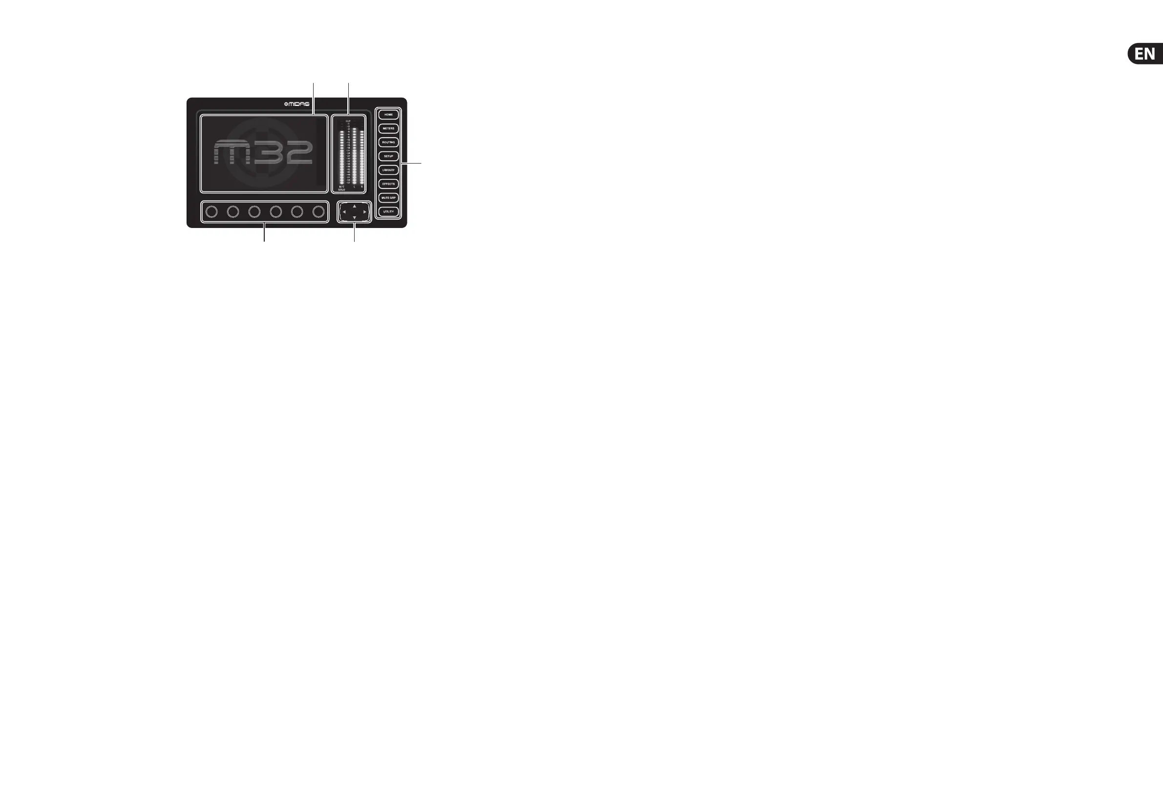
(1) DISPLAY SCREEN - The controls in this section
are used in conjunction with the colour screen
in order to navigate and control the graphical
elements it contains.
By including dedicated rotary controls that
correspond to the adjacent controls on the
screen, as well as including cursor buttons,
theuser can quickly navigate and control all of
the colour screen’s elements.
The colour screen contains various displays
that give visual feedback for the operation of
the console, and also allow the user to make
various adjustments not provided for by the
dedicated hardware controls.
(2) MAIN/SOLO METERS - This triple 24-segment
meter displays the audio signal level output
from the main bus, as well as the main centre
or solo bus of the console.
(3) SCREEN SELECTION BUTTONS - These
eight illuminated buttons allow the user to
immediately navigate to any of the eight
master screens that address di erent sections
of the console. The sections that can be
navigated are:
• • HOME - The HOME screen contains an
overview of the selected input or output
channel, and o ers various adjustments
not available through the dedicated top-
panel controls.
The HOME screen contains the following
separate tabs:
home: General signal path for the
selected input or output channel.
con g: Allows selection of the signal
source/destination for the channel,
con guration of insert point, and
other settings.
gate: Controls and displays the channel
gate e ect beyond those o ered by the
dedicated top-panel controls.
dyn: Dynamics - controls and displays the
channel dynamics e ect (compressor)
beyond those o ered by the dedicated
top-panel controls.
eq: Controls and displays the channel
EQ e ect beyond those o ered by the
dedicated top-panel controls.
sends: Controls and displays for channel
sends, such as sends metering and
send muting.
main: Controls and displays for the
selected channel’s output.
• • METERS - The meters screen displays
di erent groups of level meters for
various signal paths, and is useful for
quickly ascertaining if any channels need
level adjustment. Since there are no
parameters to adjust for the metering
displays, none of the metering screens
contain any ‘bottom of the screen’
controls that would normally be adjusted
by the six rotary controls.
The METER screen contains the following
separate screen tabs, each containing
level meters for the relevant signal paths:
channel, mix bus, aux/fx, in/out and rta.
• • ROUTING - The ROUTING screen is where
all signal patching is done, allowing
the user to route internal signal paths
to and from the physical input/output
connectors located on the console’s
rear panel.
The ROUTING screen contains the
following separate tabs:
home: Allows patching of physical inputs
to the 32 input channels and aux inputs of
the console.
out 1-16: Allows patching of internal
signal paths to the console’s 16 rear panel
XLR outputs.
aux out: Allows patching of internal signal
paths to the console’s six rear panel ¼" /
RCA auxiliary outputs.
p16 out: Allows patching of internal signal
paths to the 16 outputs of the console’s
16-channel P16 Ultranet output.
card out: Allows patching of internal
signal paths to the 32 outputs of the
expansion card.
aes50-a: Allows patching of internal
signal paths to the 48 outputs of the rear
panel AES50-A output.
aes50-b: Allows patching of internal
signal paths to the 48 outputs of the rear
panel AES50-B output.
xlr out: Allows the user to con gure the
XLR outs on the rear of the console in
blocks of four, from either local inputs,
the AES streams, or expansion card.
• • SETUP - The SETUP screen o ers controls
for global, high-level functions of the
console, such as display adjustments,
sample rates & synchronisation, user
settings, and network con guration.
The SETUP screen contains the following
separate tabs:
global: This screen o ers adjustments
for various global preferences of how the
console operates.
con g: This screen o ers adjustments for
sample rates and synchronisation, aswell
as con guring high-level settings for
signal path buses.
remote: This screen o ers di erent
controls for setting up the console as a
control surface for various DAW recording
software on a connected computer. It also
con gures the MIDI Rx/Tx preferences.
network: This screen o ers di erent
controls for attaching the console to a
standard Ethernet network. (IP address,
Subnet Mask, Gateway.)
scribble strip: This screen o ers controls
for various customisation of the console’s
LCD scribble strips.
preamps: Shows the analogue gain for
local mic inputs (XLR at the rear) and
phantom power, including setup from
remote stage boxes (e.g. DL16) connected
via AES50.
card: This screen selects the input/
output con guration of the installed
interface card.
• • LIBRARY - The LIBRARY screen allows
loading and saving of commonly-used
setups for the channel inputs, e ects
processors, and routing scenarios.
The LIBRARY screen contains the
following tabs:
channel: This tab allows the user to load
and save commonly used combinations
of the channel processing, including
dynamics andequalisation.
e ects: This tab allows the user to
load and save commonly used e ects
processor presets.
routing: This tab allows the user to load
and save commonly used signal routings.
• • EFFECTS - The EFFECTS screen controls
various aspects of the eight e ects
processors. On this screen the user
can select speci c types of e ects for
the eight internal e ects processors,
con gure their input and output paths,
monitor their levels, and adjust the
various e ects parameters.
The EFFECTS screen contains the
following separate tabs:
home: The home screen provides a
general overview of the virtual e ects
rack, displaying what e ect has been
inserted in each of the eight slots, as well
as displaying input/output paths for each
slot and the I/O signal levels.
fx1-8: These eight duplicate screens
display all of the relevant data for
the eight separate e ects processors,
allowing the user to adjust all parameters
for the selected e ect.
• • MUTE GRP - The MUTE GRP screen allows
for quick assignment and control of the
console’s six mute groups, and o ers two
separate functions:
1. Mutes the active screen during the
process of assigning channels to
mute groups. This ensures that no
channels are accidentally muted
during the assignment process
during a live performance.
2. It o ers an additional interface
for muting/unmuting the groups
in addition to the dedicated mute
group buttons at the bottom of
the console.
• • UTILITY - The UTILITY screen is a
supplemental screen designed to work in
conjunction with the other screens that
may be in view at any particular moment.
The UTILITY screen is never seen by itself,
it always exists in the context of another
screen, and typically brings up copy, paste
and library or customisation functions.
(4) ROTARY CONTROLS - These six rotary controls
are used to adjust the various elements
located directly above them. Each of the six
controls can be pushed inward to activate a
button-press function. This function is useful
when controlling elements that have a dual
on/o status that is best controlled by a
button, as opposed to a variable state that is
best adjusted by a rotary control.
(5) UP/DOWN/LEFT/RIGHT NAVIGATION
CONTROLS - The LEFT and RIGHT controls
allow for left-right navigation among the
di erent pages contained within a screen
set. A graphical tab display shows which
page you are currently on. On some screens
there are more parameters present than
can be adjusted by the six rotary controls
underneath. In these cases, use the UP
and DOWN buttons to navigate through
any additional layers contained on the
screen page. The LEFT and RIGHT buttons
are sometimes used to con rm or cancel
con rmation pop-ups.
Please refer to the User Manual for more information
on each of these topics.

 Loading...


