iii
TABLE OF CONTENTS
SECTION 1 - DESCRIPTION Page
I. OVEN USES ……………...…….………..1
II. OVEN COMPONENTS …….……………1
A. Conveyor Motor Drive
B. Crumb Pans
C. Conveyor
D. End Plugs
E. Eyebrows
F. Window
G. Control Cabin Door
H. Serial Plate
I. Control Panel
J. Photo Sensor
K. Optional Door Photo Sensor
L. Circuit Breaker Resets
M. Gas Burner
N. Blowers
O. Air FIngers
III. OVEN SPECIFICATIONS……………….2
A. Dimensions ……………………..……2
B. General Specifications ………….…..2
C. Electrical Specifications ……………2A
D. Gas Specifications ………………….2B
SECTION 2 - INSTALLATION
I. GENERAL ………………………… 3
II. BASE/TOP KITS & EQUIPMENT…………4
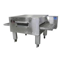
A. SINGLE OVEN BASE/TOP KIT ……..5
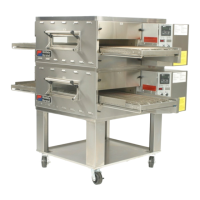
B. DOUBLE OVEN BASE/TOP KIT ……6
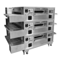
C. TRIPLE OVEN BASE/TOP KIT ……..7
III. OVEN LAYOUTS
A. Single Oven Stacked ………..….…… 8
B. Double Oven Stacked…………. ……. 10
IV. VENTILATION SYSTEM..………………..12
A. Requirements ……………………….12
B. Recommendations ………………….12
C. Other Ventilation Concerns ………..12
V. ASSEMBLY
A. Top Panel and Base Pad Assembly.13
B. Stacking ………………………………14
C. Restraint Cable Installation………….14
D. Conveyor Installation ………………..15
E. Final Assembly ……………………… 16
VI. ELECTRICAL SUPPLY ………………….17
VII. GAS SUPPLY
A. Gas Rough-In Recommendations….19
B. Connection……………………………19
C. Gas Conversion………………………19
D. ULPG Conversion………….…………20
E. Adjusting Max Pressure Setting…….20
F. Checkout………………………………20
G. Maintenance…………………………..20
H.
Gas Train with Orificed By-Pass ……20
I.
Gas Specifications………………….21-23
SECTION 3 - OPERATION
I. DESCRIPTION OF CONTROLS ……………..24
II. NORMAL OPERATION
A. Daily Oven Start-Up Procedure………….25
B. Daily Shut-Down Procedure………………25
C. Ignition Sequence of Operation …………26
D. Energy Management …………………….26
II. OTHER ADJUSTMENTS (MANAGER MODE)
A. PLC System Control Setup…………....... 27
B. B.MenuSelect Optional Program ..28
IV. TROUBLESHOOTING INFORMATION
A. Troubleshooting Guide……………………29
B. Alerts, Errors and Remedies……………..30
SECTION 4 - MAINTENANCE
I. MAINTENANCE – DAILY………………………31
II. MAINTENANCE – MONTHLY…………………32
III. MAINTENANCE – 3 MONTH…………………..33
IV. MAINTENANCE – 6 MONTH…………………..34
V. KEY SPARE PARTS………………………. 34-35
SECTION 5 – WIRING DIAGRAM ….……......... 36
SECTION – ASSEMBLY DRAWINGS….......... 41
 Loading...