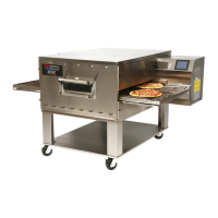
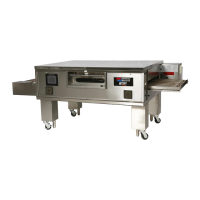
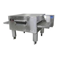
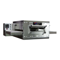
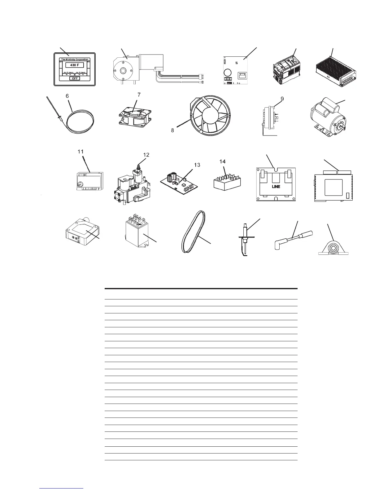
V. KEY SPARE PARTS – Available separately. See Figure 4-8.
KEY SPARE PARTS PS640 GAS
ITEM QTY. P/N DESCRIPTION
1 1 60190 Digital Display, Programmed
2 1 58920 Motor, Conveyor Drive
3 1 58679 Conveyor Control Board
4 1 60192 Inverter, Programmed
5 1 M9608 Power Supply
6 1 60196 Kit, Thermocouple
7 1 97525 Fan Cooling Control
8 1 51399 Fan Cooling Rear
9 1 60598 Air Switch
10 1 57288 Motor, Blower
11 1 50239 Ignition Module
12 1 60679 Assy, Valve Gas Modulating
13 1 60671 Board, Signal Cond. 0-15VDC
14 1 33983 High Limit Control Module,240V
15 2 32108 Transformer,240Vp:24Vs
16 1 60193 PLC ModuIe, Programmed
17 1 58668 Thermocouple Module
18 1 58669 Current Module
19 1 60251 PhotoCell
20 2 59132 Relay, DPDT 24V Coil
21 1 59668 Belt, Blower
22 1 48455 Ignitor, Single Rod
23 1 50240 Ignition Cable, 25″
24 1 60636 Bearing, PB 5/8 B
Figure 4-8. Key Spare Parts
12 345
15
27
10
16, 17, 18
19
20
21
22
23
24
 Loading...