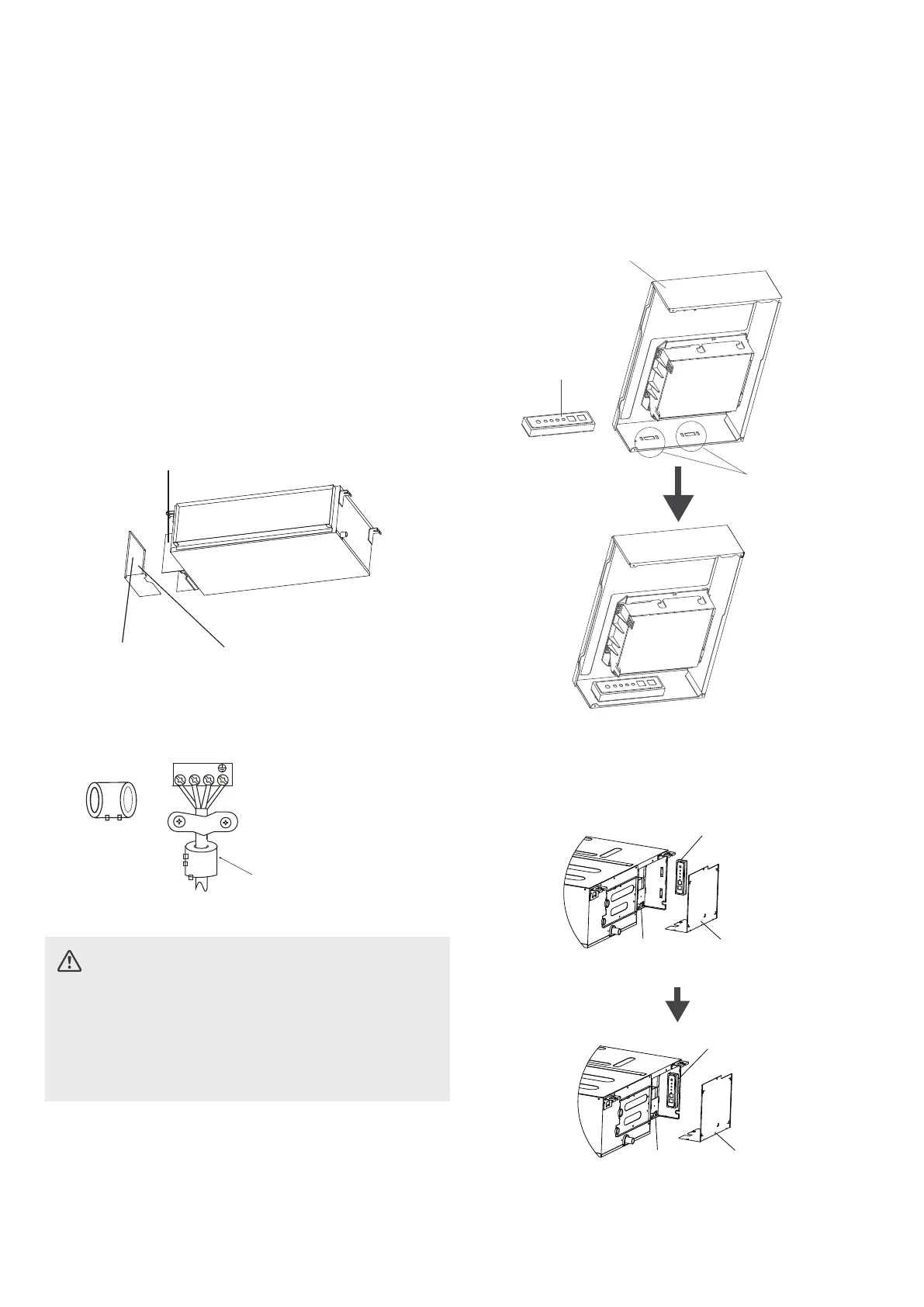
Magnetic ring (if supplied and packed with the
accessories)
1 2 3
Pass the belt through
the hole of the Magnetic
ring to fix it on the cable
INDOOR UNIT WIRING
CAUTION
• While connecting the wires, please strictly
follow the wiring diagram.
• The refrigerant circuit can become very hot.
Keep the interconnection cable away from the
copper tube.
1. Prepare the cable for connection.
a. Using wire strippers, strip the rubber jacket
from both ends of the signal cable to reveal
about 15cm (5.9”) of the wire.
b. Strip the insulation from the ends of the
wires.
c. Using a wire crimper, crimp the u-lugs to
the ends of the wires.
2.
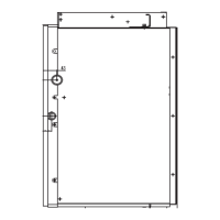
Remove the cover of the electric control box
on your indoor unit.
3.
Connect the u-lugs to the terminals.
Match the wire colors/labels with the labels
on the terminal block. Firmly screw the
u-lug of each wire to its corresponding
terminal. Refer to the Serial Number and
Wiring Diagram located on the cover of the
electric control box.
Connective
wiring diagram
Wiring
diagram
Control box
28
4. Clamp down the cable with the cable clamp.
The cable must not be loose or pull on the
u-lugs.
If there is a component of display control unit,
when installing the component of display
control unit, it needs to be fixed at the snap
position in the electric control box.
Electric control box
Component of
display control
unit
Snap position
6. Reattach the electric box cover.
Electric control
box cover
Display box
Electric
control box
Electric control
box cover
Display box
Electric
control box
5. The display box needs to be installed in the
electric control box, the display box needs to
be installed inside the electric control, stuck
on the electric control box sheet metal clips.