The first code and the second represent the first level
and the second level menu from the field set list.
The last two numbers indicate the value of the first and
the second code.
3.2 Setting Procedure
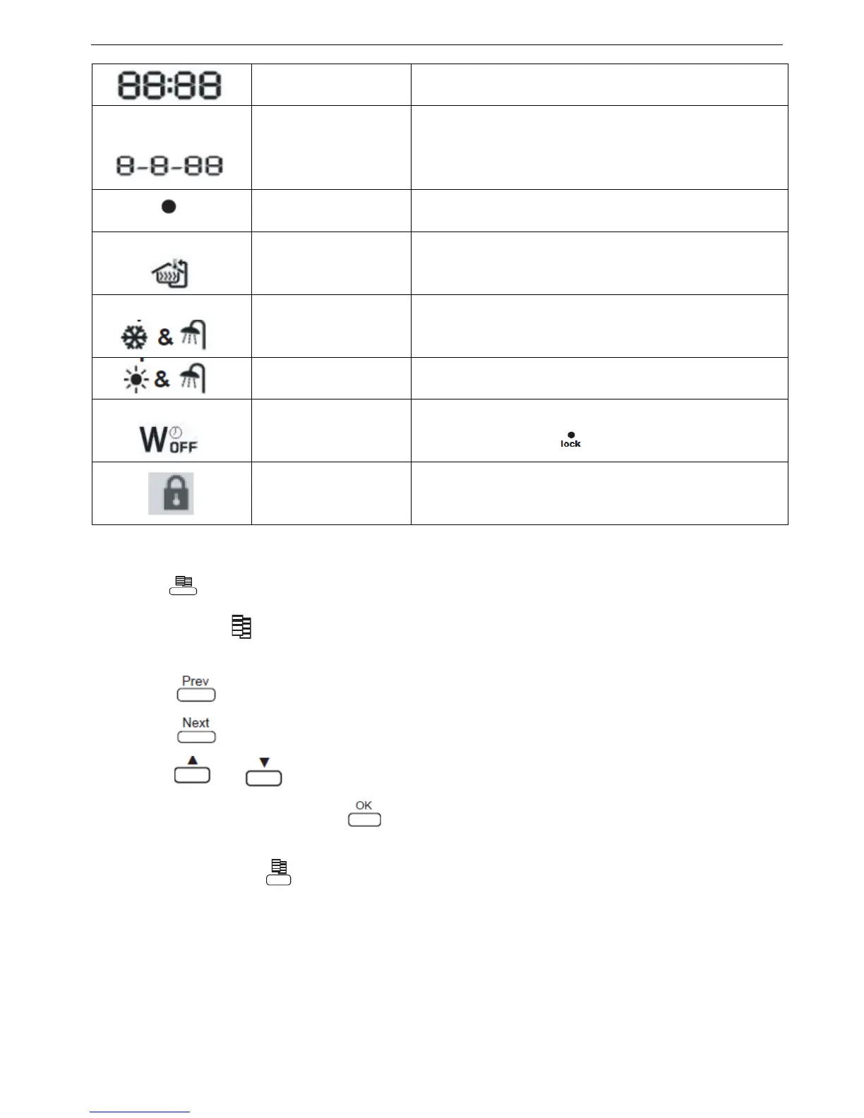
1 Press the button to enter FIELD SET MODE .
The SETTING icon will be displayed. The current selected field setting code is indicated “8-8-88”,
with the set value displayed as the last 2-digit number.
2 Press the button to select the appropriate field setting first code.
3 Press the button to select the appropriate field setting second code.
4 Press the and button to change the set value of the select field setting.
5 Save the new value by pressing the button.
6 Repeat step 2 through 4 to change other field settings as required.
7 When finished, press the button for the second time to exit.
Note: Please read the manual carefully to understand how to operate wire controller
3.3 Detailed description
a) Basic option
This part of field setting determines the basic option of the heat pump system, so that the control system can
select the appropriate control mode.
“0-0” Under floor heating terminal: defines whether the system installations with under floor
 Loading...