02
3 ACCESSORIES
Table.3-1
Accessory
Name
Qty Shape Explanation
Installation
Manual
1
Installation and use
instruction
Electric
control box
1 -
Control the power supply
of electric heater (Only with
e-heater)
4 INSTALLATION LOCATION
• Enough space for installation and maintenance shall
be preserved.
• The bearing surface should be flat and able to bear
weight of the unit.
• Convenient for piping and wiring.
• If the unit need to be installed on a metal holder, make
sure they are insulated well and in accordance with local
standard.
CAUTION
• Installing the equipment in any of the follow- ing
places may lead to malfunction of the equipment (if it is
inevitable, consult the supplier):
• The site contains mineral oils such as cutting
lubricant. Seaside where the air contains much salt.
• Hot spring area where corrosive gases exist,
e.g., sulfide gas. Factories where the power voltage
fluctuates seriously.
• Place like kitchen where oil permeates.
• Place where strong electromagnetic waves exist.
• Place where acid or alkali gases evaporate.
• Other special environments.
Precautions before installation
• Decide the correct way of conveying the equipment.
• If the unit has to be installed on a metal part of the
building, electric insulation must be installed, and the
installation must meet the relevant technical standards for
electric devices.
Installation space
• Before installing the unit, reserve the space of
maintenance shown in the following figure.
Fig.4-1
400
45°
90°
19°
Fig.4-2
≥300 mm
5 INSTALLATION
WARNING
Ask your supplier to install the units. Incom- plete
installation performed by yourself may result in a water
leakage, electric shock, or fire.
In the place where there is strong wind like seashore,
fix the unit in the location protected from the wind.
5.1 Unpack and move
• This product is very heavy, it need to be carried by
2 or more persons, otherwise might cause injury and
damage. Or you can use a forklift to move.
• Make sure there is enough installation space.
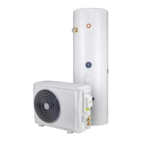
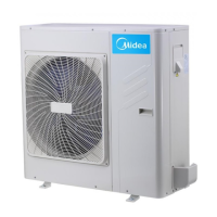
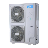
• Outline dimensional drawing(see Fig 5-1, Fig 5-2).
Fig.5-1
Coil Inlet
(G3/4”)
Coil Outlet
(G3/4”)
TP Valve
(G3/4”)
Anode Rod
(G3/4”)
Temperature
Sensor of Water
Tank (G1/2”)
Water Inlet/Drain
Pipe (G3/4”)
Solar Water
Outlet (G3/4”)
Solar Water
Inlet (G3/4”)
Hot Water
Outlet (G3/4”)