Installation
Page 121
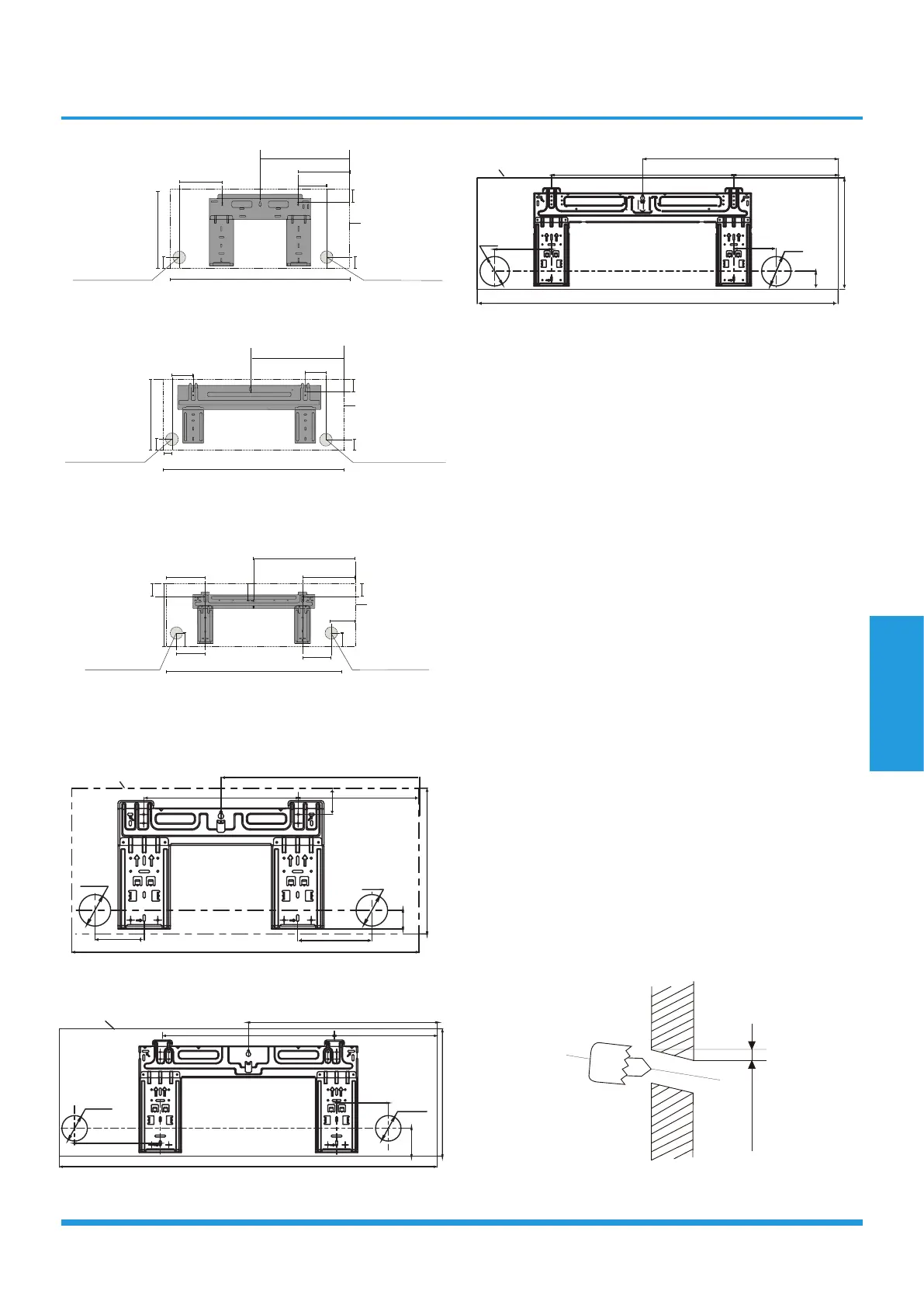
192mm (7.55in)
232mm (9.15in)
128mm (5.05in)
43mm (1.7in)
297mm (11.7in)
Left rear wall
hole 65mm (2.5in)
Right rear wall
hole 65mm (2.5in)
Indoor unit outline
802mm (31.6in)
43mm (1.7in)
12K Model
144mm (5.65in)
58mm (2.3in)
319mm (12.55in)
57mm (2.25in)
Right rear wall
hole 65mm (2.5in)
965mm (38in)
138mm (5.45in)
34mm (1.35in)
Indoor unit outline
517.4mm (20.37in)
18K Model
219mm (8.6in)
553mm (21.77in)
300mm (11.8in)
Left rear wall
hole 65mm (2.5in)
Right rear wall
hole 65mm (2.5in)
1080mm (42.5in)
53.5mm
(2.1in)
47mm (1.85in)
76mm(3in)
53.5mm (2.1in)
47mm (1.85in)
148.7mm
(5.85in)
151mm (5.95in)
174.3mm (6.85in)
Indoor unit outline
24K Model
For All Easy series:
302mm(11.9in)
805mm(31.7in)
406.4mm(16in)
249mm(9.8in)
153mm(6in)102mm(4in)
pipe hole
φ
65mm
2.56 in)
pipe hole
φ
65mm
(2.56 in)
Indoor unit outline
54mm(2.1in)
9K/12K Model
964mm(37.9in)
482mm(19in)
325mm(12.8in)
pipe hole
φ
65mm
(2.56 in)
pipe hole
φ
65mm
(2.56 in)
132mm
(5.20in)
219mm(8.62in)
262mm(10.31in)439mm(17.28in)
18K Model
1106mm(43.5in)
599mm(23.6in)
342mm(13.5in)
pipe hole
φ
65mm
2.56 in)
pipe hole
φ
65mm
(2.56 in)
Indoor unit outline
174mm
(6.85in)
320mm(12.60in)
130mm
(5.12in)
558mm(21.97in)
24K Model
• Note for concrete or brick walls:
If the wall is made of brick, concrete, or similar material,
drill 5mm-diameter (0.2in-diameter) holes in the wall
and insert the sleeve anchors provided. Then secure the
mounting plate to the wall by tightening the screws
directly into the clip anchors.
3.3 Drill wall hole for connective piping
You must drill a hole in the wall for refrigerant piping, the
drainage pipe, and the signal cable that will connect the
indoor and outdoor units.
1. Determine the location of the wall hole based on the
position of the mounting plate. Refer to Mounting Plate
Dimensions on the next page to help you determine the
optimal position. The wall hole should have a 65mm
(2.5in) diameter at least, and at a slightly lower angle to
facilitate drainage.
2. Using a 65mm (2.5in) or 90mm(3.54in) (depending on
models )core drill, drill a hole in the wall. Make sure that
the hole is drilled at a slight downward angle, so that the
outdoor end of the hole is lower than the indoor end by
about 5mm to 7mm (0.2-0.27in). This will ensure proper
water drainage.
3. Place the protective wall cuff in the hole. This protects
the edges of the hole and will help seal it when you finish
the installation process.
NOTE: When drilling the wall hole, make sure to avoid
wires, plumbing, and other sensitive components.
Wall
Indoor Outdoor
mm7-5
(0.2-0.27in)
 Loading...