Installation
Page 122
3.4 Prepare refrigerant piping
The refrigerant piping is inside an insulating sleeve
attached to the back of the unit. You must prepare the
piping before passing it through the hole in the wall.
Refer to the Refrigerant Piping Connection section of this
manual for detailed instructions on pipe flaring and flare
torque requirements, technique, etc.
1. Based on the position of the wall hole relative to the
mounting plate, choose the side from which the piping will
exit the unit.
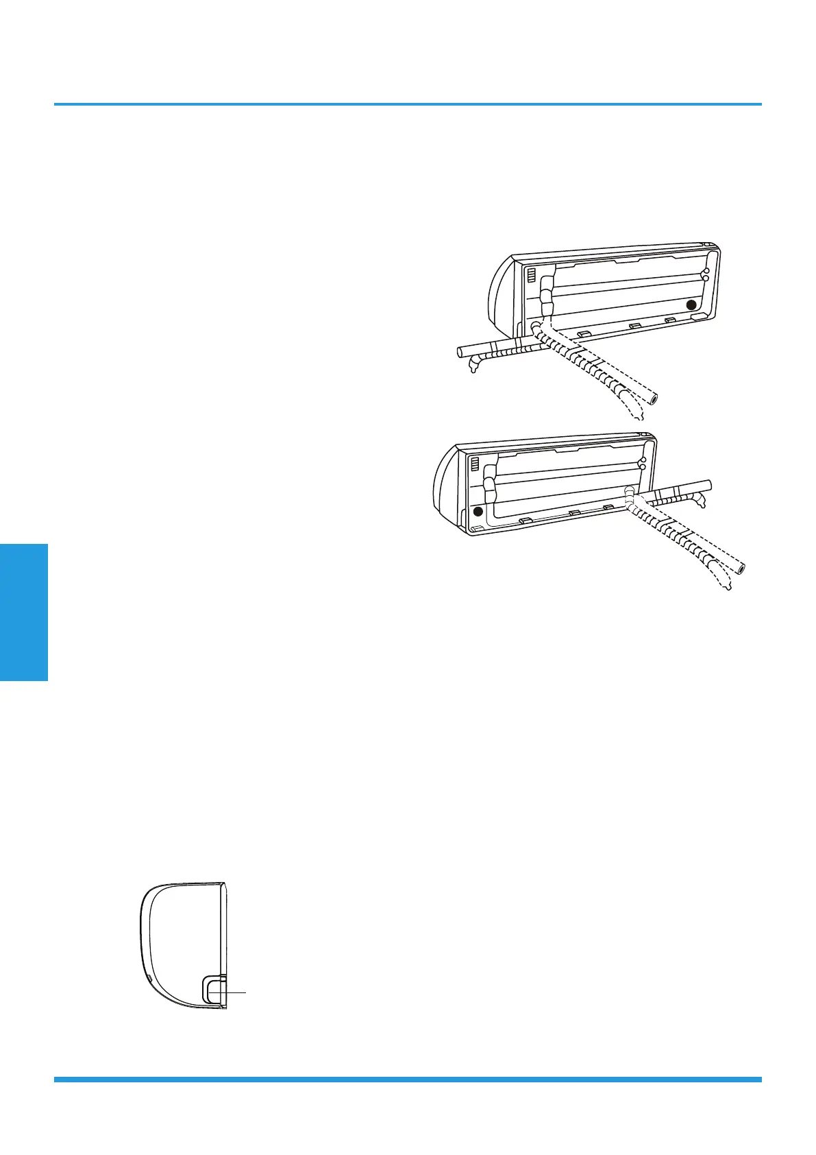
2. If the wall hole is behind the unit, keep the knock-out
panel in place. If the wall hole is to the side of the indoor
unit, remove the plastic knock-out panel from that side of
the unit. This will create a slot through which your piping
can exit the unit. Use needle nose pliers if the plastic panel
is too difficult to remove by hand.
3. Groove has been made in the knock-out panel in order
to cut it conveniently. The size of the slot is determined by
the diameter of piping.
4. Use scissors to cut down the length of the insulating
sleeve to reveal about 15cm (6in) of the refrigerant piping.
This serves two purposes:
• To facilitate the Refrigerant Piping Connection
process.
• To facilitate Gas Leak Checks and enable you to check
for dents.
5. If existing connective piping is already embedded in the
wall, proceed directly to the Connect Drain Hose step. If
there is no embedded piping, connect the indoor unit’s
refrigerant piping to the connective piping that will join the
indoor and outdoor units. Refer to the Refrigerant Piping
Connection section of this manual for detailed instructions.
6. Based on the position of the wall hole relative to the
mounting plate, determine the necessary angle of your
piping.
7. Grip the refrigerant piping at the base of the bend.
8. Slowly, with even pressure, bend the piping towards
the hole. Do not dent or damage the piping during the
process.
Knock-out Panel
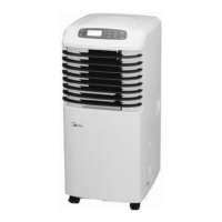
NOTE: Refrigerant piping can exit the indoor unit from
four different angles:
• Left-hand side
• Left rear
• Right-hand side
• Right rear
Be extremely careful not to dent or damage the piping
while bending them away from the unit. Any dents in the
piping will affect the unit’s performance.
3.5 Connect drain hose
By default, the drain hose is attached to the left
hand side of unit (when you’re facing the back
of the unit). However, it can also be attached to
the right-hand side.
1. To ensure proper drainage, attach the drain
hose on the same side that your refrigerant
piping exits the unit.
2. Attach drain hose extension (purchased
separately) to the end of drain hose.
3. Wrap the connection point firmly with Teflon
tape to ensure a good seal and to prevent leaks.
4. For the portion of the drain hose that
will remain indoors, wrap it with foam pipe
insulation to prevent condensation.
5. Remove the air filter and pour a small amount
of water into the drain pan to make sure that
 Loading...