CAUTION
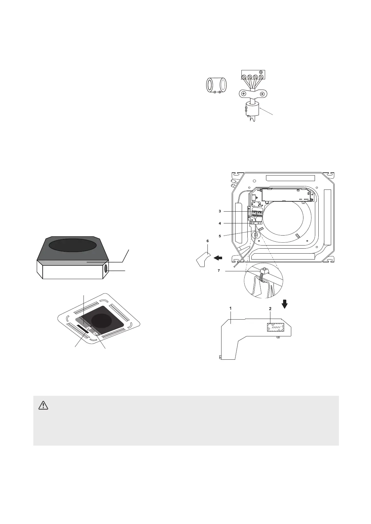
Compact models
1 Control box lid
2 Wiring diagram label
3 Power supply terminal block
4 Clamp for wiring
5 Wiring between units
6 Plastic cover
7 Clamp (field supply)
Magnetic ring (if supplied and packed with the
accessories)
1 2 3
Pass the belt through
the hole of the Magnetic
ring to fix it on the cable
Super-Slim models
Wire outlet
Control box
Connective wiring diagram
Wiring diagram
Control box
1. Prepare the cable for connection
a. Using wire strippers, strip the rubber jacket
from both ends of the signal cable to reveal
about 15cm (5.9”) of the wire.
b. Strip the insulation from the ends of the
wires.
c. Using a wire crimper, crimp the u-lugs to
the ends of the wires.
2. Open the front panel of the indoor unit. Using
a screwdriver,remove the cover of the electric
control box on your indoor unit.
3. Thread the power cable and the signal cable
through the wire outlet.
4. Connect the u-lugs to the terminals.
Match the wire colors/labels with the labels on
the terminal block. Firmly screw the u-lug of
each wire to its corresponding terminal. Refer
to the Serial Number and Wiring Diagram
located on the cover of the electric control box.
NOTE: The actual shape of your unit may be
slightly dierent. The actual shape shall prevail.
OUTDOOR UNIT WIRING
• While connecting the wires, please strictly follow the wiring diagram.
• The refrigerant circuit can become very hot. Keep the interconnection cable away from the
copper tube.
5. Clamp down the cable with the cable clamp.The cable must not be loose or pull on the u-lugs.
6. Reattach the electric box cover.
28