MCAC-ATSM-2014-09 R410a tropical air-cooled scroll chiller unit 60Hz
Installation 141
Multi-module combination installation involves special design of the unit, so relevant explanation is
given as follows.
Installation mode of multi-module combination water system pipeline
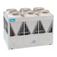
1) Installation mode I (recommended installation mode)
No.1 unit
No.0 address(main unit)
No.n unit (n≤5)No.(n-1) unit
No.(3n-4) address No.(3n-1) address
No.1 address No.(3n-5) address No.(3n-2) address
Pump
No.2 address No.(3n-6) address No.(3n-3) address
Drill dead hole at the
position, and move the
total effluent temperature
sensor at No.0 address to
the position
Water flow switch
n : the module quantity, max5
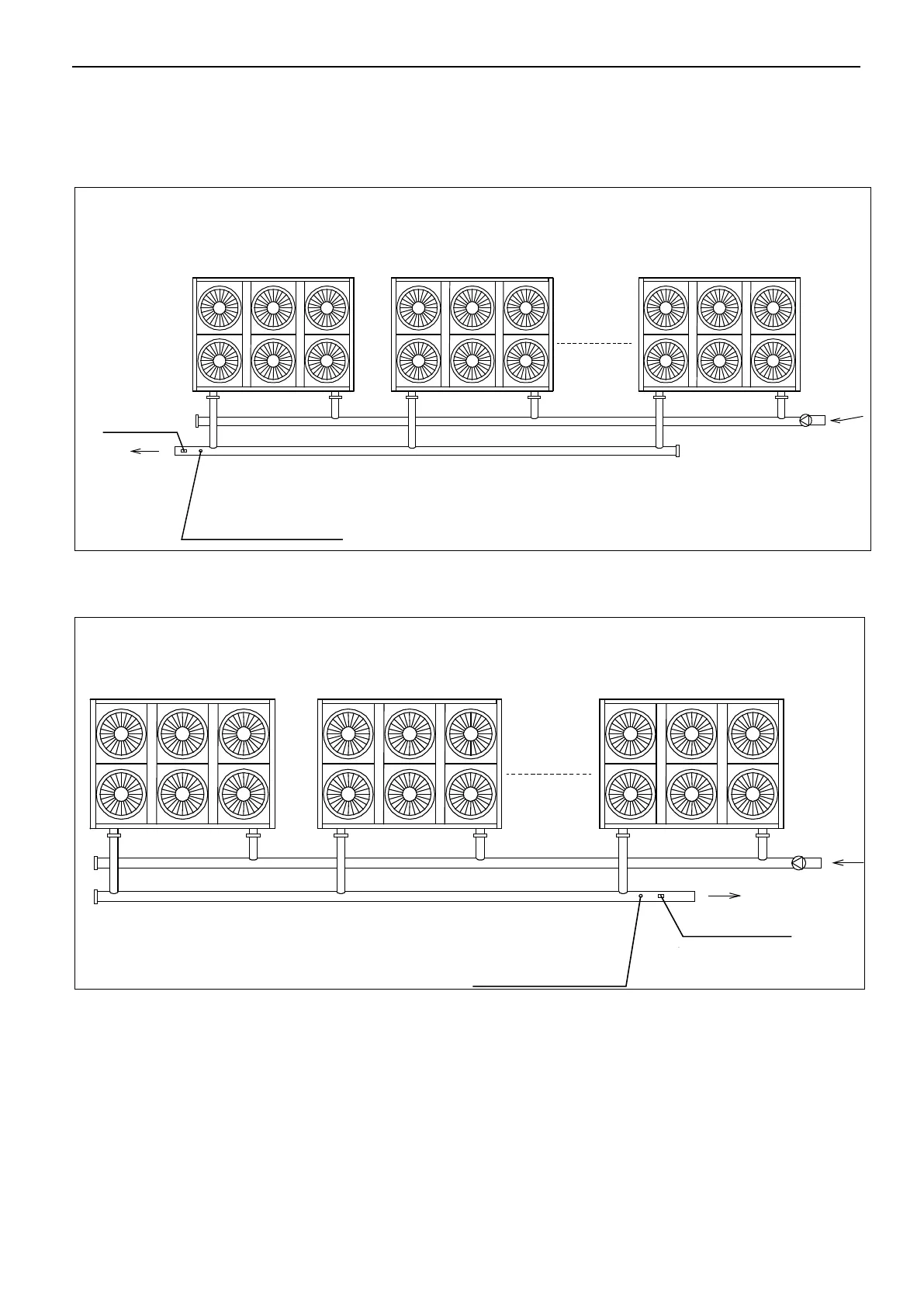
2) Installation mode II
Fig.4-9(less than 5 modules)
Water flow switch
Drill dead hole at the
position, and move the
total effluent temperature
sensor at No.0 address to
the position
No.1 unit
No.0 address(main unit)
No.n unit (n≤5) No.(n-1) unit
No.(3n-4) addressNo.(3n-1) address
No.1 addressNo.(3n-5) addressNo.(3n-2) address
No.2 addressNo.(3n-6) addressNo.(3n-3) address
Pump
n : the module quantity, max5
Please pay attention to the following items when installing multiple modules:
● Each module corresponds to an address code
which cannot be repeated.
● Main water outlet temperature sensing bulb, target
flow controller and auxiliary electric heater are under
control of the main module.
● One wired controller and one target flow controller
are required and connected on the main module.
● The unit can be started up through the wired
controller only after all addresses are set and the
aforementioned items are determined. The wired
controller is ≤500m away from the outdoor unit.
 Loading...