READ THESE INSTRUCTIONS CAREFULLY BEFORE
INSTALLATION. KEEP THIS MANUAL IN A HANDY PLACE
FOR FUTURE REFERENCE.
IMPROPER INSTALLATION OR ATTACHMENT OF
EQUIPMENT OR ACCESSORIES COULD RESULT IN
ELECTRIC SHOCKS, SHORT-CIRCUITS, LEAKS, FIRE OR
OTHER DAMAGE TO THE EQUIPMENT. BE SURE TO
ONLY USE ACCESSORIES MADE BY THE SUPPLIER
WHICH ARE SPECIFICALLY DESIGNED FOR USE WITH
THE EQUIPMENT AND HAVE INSTALLATION DONE BY A
PROFESSIONAL
ALL ACTIVITIES DESCRIBED IN THIS MANUAL SHALL BE
CARRIED OUT BY A LICENSED TECHNICIAN.
BE SURE TO WEAR ADEQUATE PERSONAL
PROTECTION SUCH AS GLOVES AND SAFETY GLASSES
WHEN PERFORMING INSTALLATION, MAINTENANCE
OR SERVICE TO THE UNIT.
IF UNSURE OF INSTALLATION PROCEDURES OR USE,
CONTACT YOUR DEALER FOR GUIDANCE
■ Domestic hot water tank (field supply)
A domestic hot water tank can be connected to the unit(with or
without electrical booster heater is both OK).
There is a heat exchanger in the tank. If the heat exchanger
outside is enameled, the heat exchanger surface must be bigger
than 1.7m
2
for matching the 10kW ~16kW unit and the heat
exchanger surface needs to be bigger than 1.4m
2
for matching the
5kW~9kW unit.
■ Room thermostat (field supply)
Room thermostat can be connected to the unit(room thermostat
should be kept away from heating source when selecting the
installation place).
■ Solar kit for domestic hot water tank (field supply)
An optional solar kit can be connected to the unit.
■ Remote alarm kit (field supply)
A remote alarm kit can be connect to the unit.
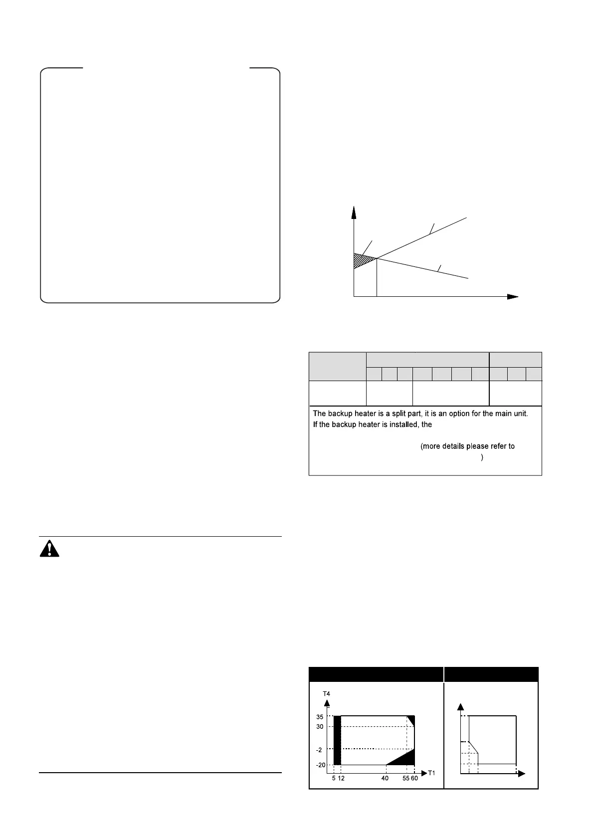
■ Operation range
1. Heat pump capacity
2. Required heating capacity (site dependent)
3. Additional heating capacity provided by backup heater
Capacity/Load
Outdoor temperatureTbivalent
1
2
3
1 INTRODUCTION
1.1 General information
■ These units are used for both heating and cooling applications.
They can be combined with fan coil units, floor heating
applications, low temperature high efficiency radiators, domestic
hot water tanks (field supply) and solar kits (field supply).
■ A wired user interface is supplied with the unit to control the
installation.
■ The unit is delivered with an integrated backup heater for
additional heating capacity during cold outdoor temperatures. The
backup heater also serves as a backup in case of malfunctioning
and for freeze protection of the outside water piping during winter
time. The capacity of backup heater for different units is listed below.
CONTENTS PAGE
1
1 INTRODUCTION.....................................................................1
2 ACCESSORIES......................................................................2
3 SAFETY CONSIDERATIONS.................................................2
4 BEFORE INSTALLATION......................................................3
5 IMPORTANT INFORMATION REGARDING THE
REFRIGERANT USED............................................................4
6 SELECTING INSTALLATION SITE........................................4
7 PRECAUTIONS ON INSTALLATION.....................................5
8 TYPICAL APPLICATION EXAMPLES...................................7
9 OVERVIEW OF THE UNIT.....................................................18
10 START-UP AND CONFIGURATION.....................................35
11 TEST RUN AND FINAL CHECK...........................................49
12 MAINTENANCE AND SERVICE...........................................49
13 TROUBLESHOOTING..........................................................49
14 TECHNICAL SPECIFICATIONS...........................................55
HEATING MODE COOLING MODE
T4
T1
20
46
-5
5 10 25
10
Unit
1-phase 3-phase
10 12 14 16 12 14 165
7
Capacity of
backup heater
4.5kW(optional)
3kW(standard)
3kW
(optional)*
4.5kW
port (CN6) for T1 in the main
control board of hydraulic should connect to the corresponding
port in the backup heater box 9.2.2
Function diagram of hydraulic compartment
9
 Loading...

