Maintenance and
Disassembly
Page 37
Procedure Illustration
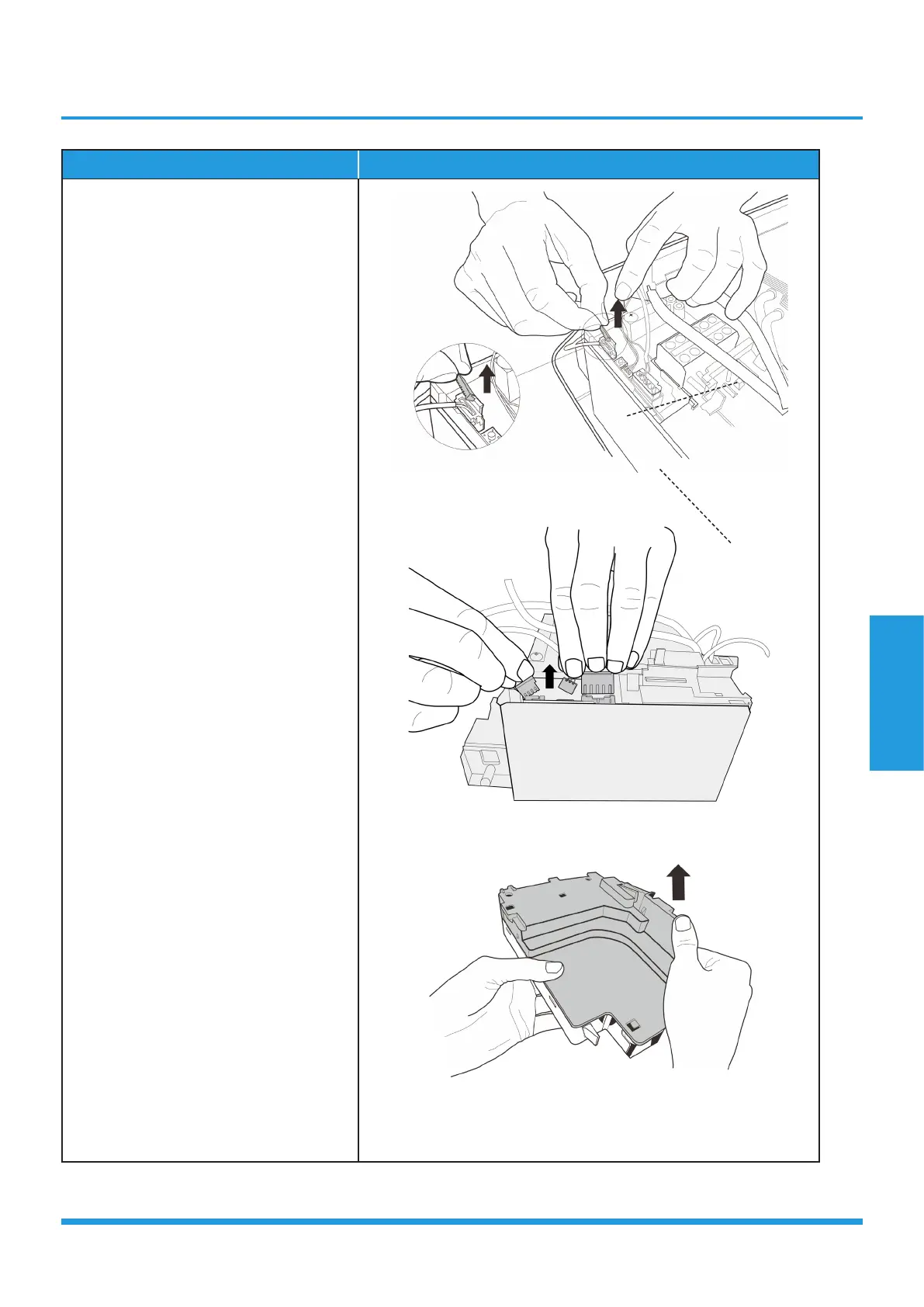
4) Remove the fixed devices of the
connectors (see CJ_MB1_INV_019).
5) Disconnect the connectors of fan
motor, the step motor and the T2
sensor (see CJ_MB1_INV_020).
6) Open the left side plate of electronic
control box (see CJ_MB1_INV_021).
CJ_MB1_INV_019
CJ_MB1_INV_020
CJ_MB1_INV_021
Note: This section is for reference only. Actual unit appearance may vary.
Main Board
Electronic Box
 Loading...