Maintenance and
Disassembly
Page 36
2. Electrical parts
Note: Remove the front panel (refer to 1. Front panel) before disassembling electrical parts.
Procedure Illustration
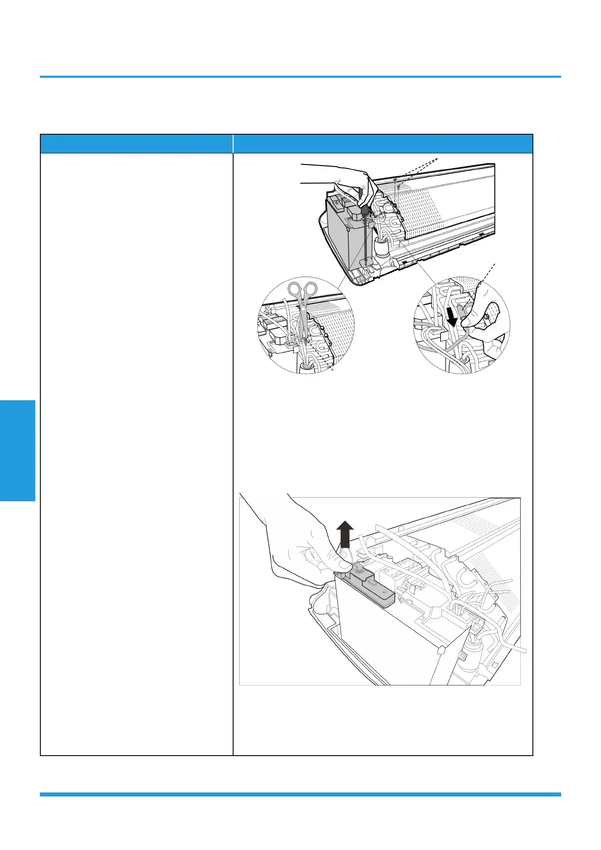
1) Cut the ribbon by a shear, then pull
out the coil temperature sensor (T2)
(see CJ_MB1_INV_017).
2) Remove one fixing screw of the
electronic control box and two screws
used for the ground connection (see
CJ_MB1_INV_017).
3) An upward force is maintained until
the cover of electronic control box is
removed (see CJ_MB1_INV_018).
CJ_MB1_INV_017
CJ_MB1_INV_018
Note: This section is for reference only. Actual unit appearance may vary.
Ribbon
T2 Sensor
Ground Screws
 Loading...