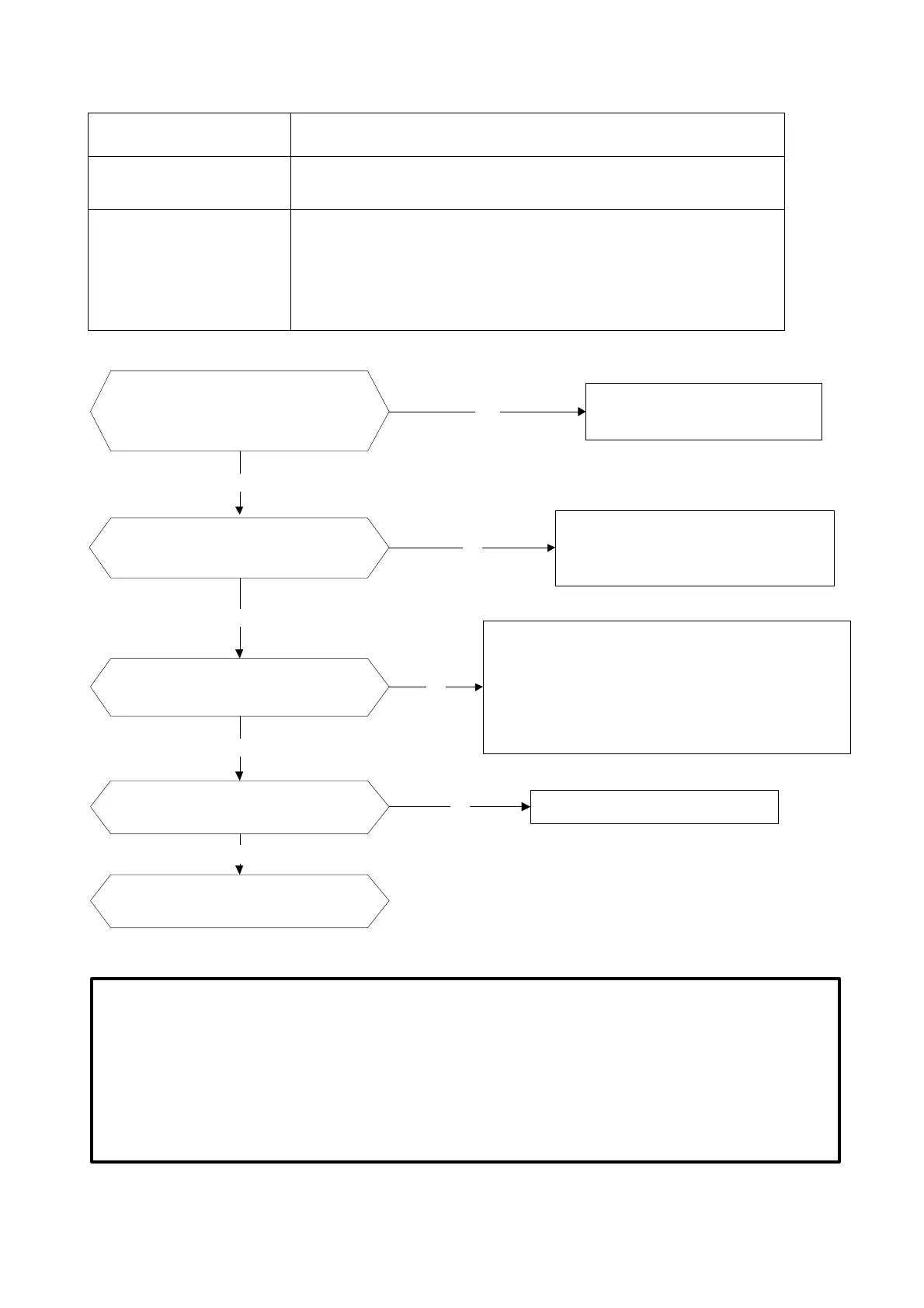
Check if the wiring between main
PCB and compressor connected by
error and if the wires and connectors
are broken?
Correct the connection or replace
the wires and connectors.
Yes
No
IPM continuity check. Check if the
IPM terminal resistance values are
uniform. Refer to page 64.
Replace the IPM board or replace the
main PCB if the IPM board and main
PCB are integrated together.
No
Check if the outdoor fan runs
properly or the outdoor unit
ventilation is good.
Yes
No
For MSV1-09HRFN1-MT0W and MSV1-12HRFN1- MT0W
models, refer to the solution of fan speed has been out
of control malfunction . Find out the cause and have it
solved. For other models, please refer to the below
remark, check whether the resistance of the fan motor
is normal. If not, replace the fan motor.
Yes
Check if the compressor resistance
values are uniform .Refer to page 63.
No
Replace the compressor.
Yes
Replace the outdoor main PCB if the
main PCB and IPM are separate.
Remark:
1) MSV1-12HRDN1-MQ0W model: Measure the black pin and red pin of the motor connector, the resistance
should be around 293Ω at 20℃(68℉)
2) MSV1-18HRDN1-MQ0W model: Measure the black pin and red pin of the motor connector, the resistance
should be around 56Ω at 20℃(68℉)
3) MSV1-24HRDN1-MQ0W model: Measure the black pin and red pin of the motor connector, the resistance
should be around 56.5Ω at 20℃(68℉)
4)
 Loading...