R410A DC Inverter VRF V4 Plus W Series 50Hz MCAC-VTSM-2016-04
180 Installation
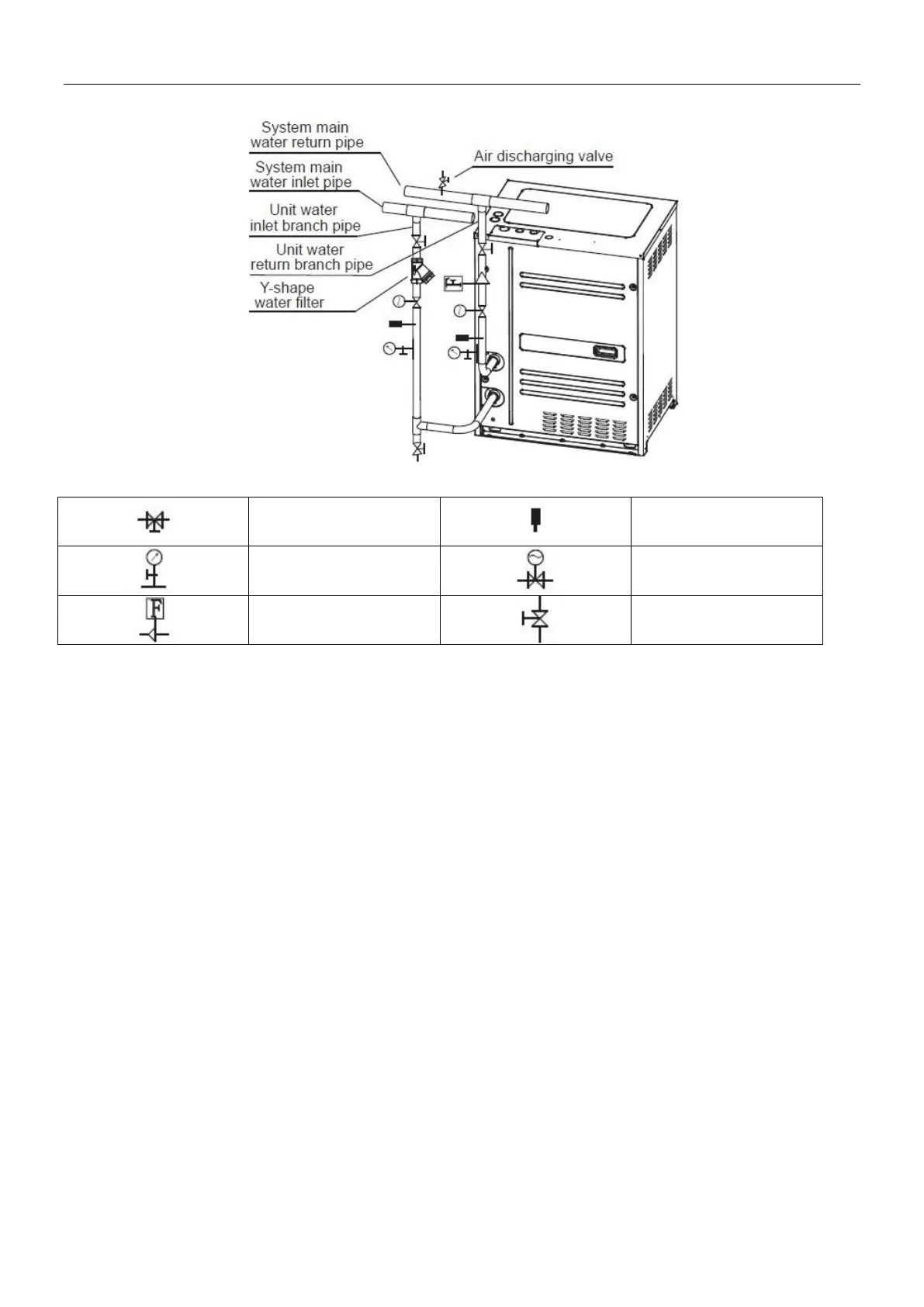
Direction schematic diagram of water system pipes
Symbols description
As the above Fig.3-5, when horizontal installing the water system main water inlet pipe and main water return
pipe, the water inlet branch pipe and water return branch pipe which connected with the unit must be separate
connected from the vertically lower direction of main water inlet pipe and main water return pipe; if connected
from the side direction and the top direction will affect the unit performance.
3.5 Installation & regulation guide for water flow switch
3.5.1. Please carefully check flow switches before conducting installation of the water flow switch. Packing
should be in good condition, and the appearance should be free of damage and deformation. If any problem,
please contact the manufacturer.
3.5.2. Flow switches can be installed in the horizontal pipeline or the vertical pipeline with upward flowing
direction but cannot be mounted in the pipeline with downward flowing direction. The inlet water of gravity
should be taken into account when flow switches are installed in the pipeline with upward flowing direction.
3.5.3. Water flow switch must be installed on a section of straight-line pipeline, and its both ends must be
supplied with straight-line pipes whose length is at least 5 times diameter of the pipe. In the meanwhile, the
fluid flowing direction in the pipeline must be consistent with the direction of arrow on the switch. The
connection terminal should be located where wiring connection can be easily done. (Fig.3-6).
3.5.4. Pay attention to the following items when conducting installation and wire connection:
1) Collision of the wrench with the soleplate of the flow switch is prohibited, since such collision may cause
deformation and failure of the flow switch.
2) To avoid electric shock and damages to the devices, the power supply should be cut off, when wires are
connected or adjustment is done.
3) When wiring connection is conducted, adjustment of other screws except connection terminals of micro
switches and ground screws is prohibited. In the meanwhile, over great force should not applied when wires of
micro switches are connected, otherwise micro switches may suffer displacement, thus leading to failure of