V6-i VRF 50/60Hz
18
Midea V6-i Series Service Manual
20/22/24HP
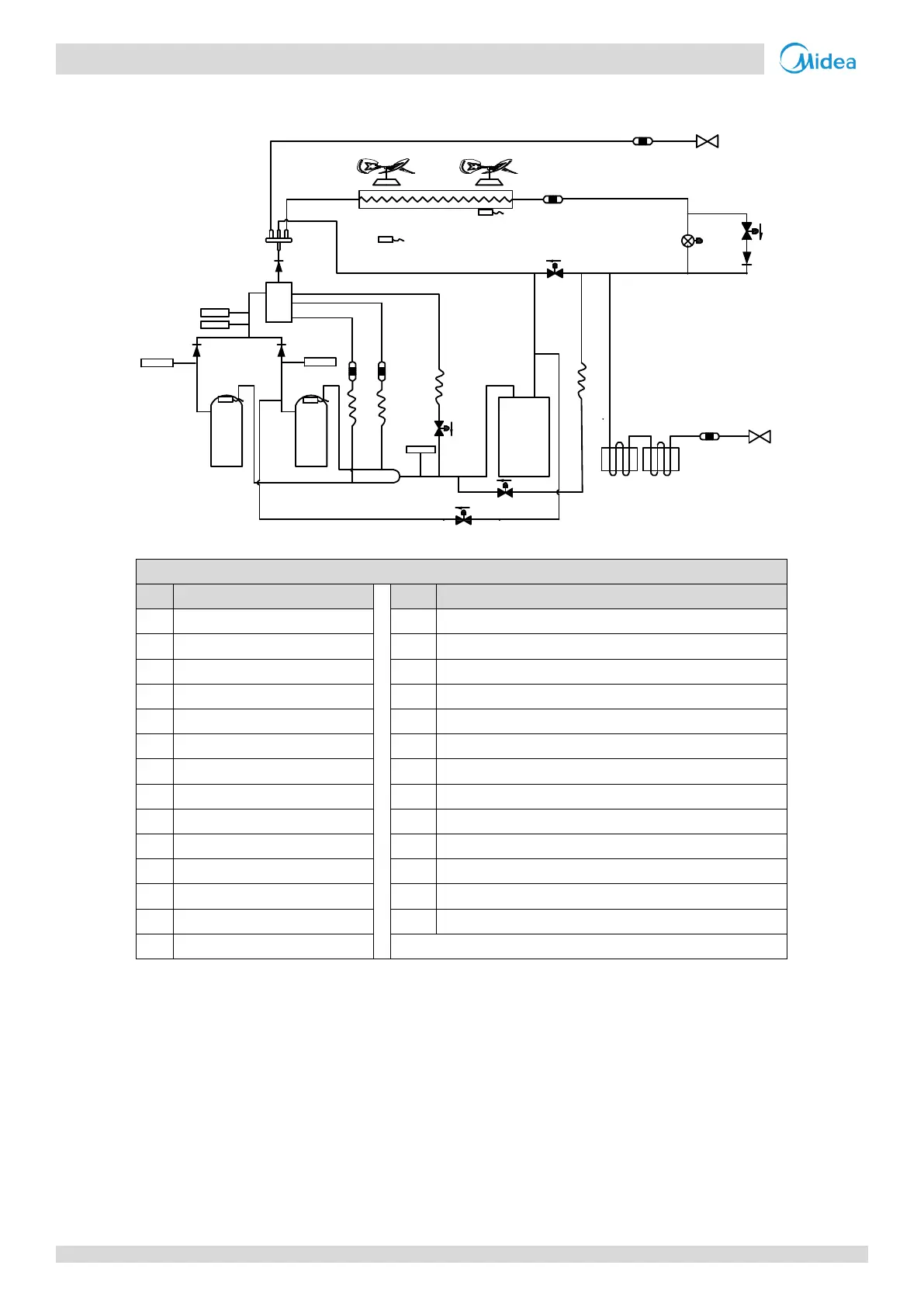
Figure 2-2.3: 20/22/24HP piping diagram
Discharge temperature switch
Heat exchanger temperature sensor
Outdoor ambient temperature sensor
Plate heat exchanger inlet temperature sensor
Plate heat exchanger outlet temperature sensor
Compressor A discharge temperature sensor
Compressor B discharge temperature sensor
Electronic expansion valve (EXV)
Fast defrosting (in heating) and unloading (in cooling) valve
Refrigerant bypass EXV valve
Compressor A vapor injection valve
Compressor B vapor injection valve
Compressor B pressure balance valve
7
1
1
15
12
9
3
4
5
6
11
11
10 10
8
13
EXVA
E
S
C
SV9
SV4
SV5
SV6
SV2
T3
T4
2
T7C1
T7C2
2
 Loading...